Attic Truss Analysis
The truss shown below is known as an Attic Truss or a Room-In Attic Truss. This type of truss carries a combination of Roof (Lr or S) and Floor (L) loading in addition to the standard top and bottom chord Dead loads. Analysis of an attic truss requires multiple load cases with multiple duration factors. It is also an indeterminate structure with a non-triangulated web area, which interrupts the normal flow of forces thru the truss. Indeterminate structures cannot be solved using the equations of static equilibrium, instead matrix analysis (direct stiffness method) is commonly employed.
The sheer number of calculations required to solve for a typical attic truss using matrix analysis is beyond what can be reasonably achieved with manual methods. Hence the use of specialized structural software in dealing with these types of structural frames. The truss shown below has been modeled with RISA3D, and the standard Axial, Shear and Moment diagrams are then generated within the software.

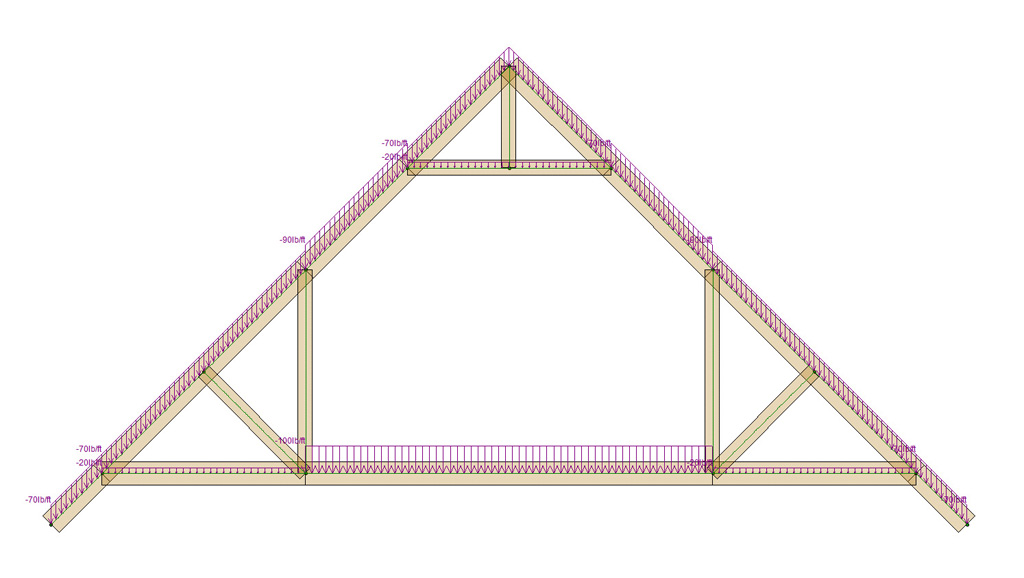
Load Diagram:
Loads for both dead and live loads are applied to the top chord, bottom chord and ceiling of the attic truss. Notice the distributed load applied to the bottom chord within the attic space is much higher due to the floor live load.
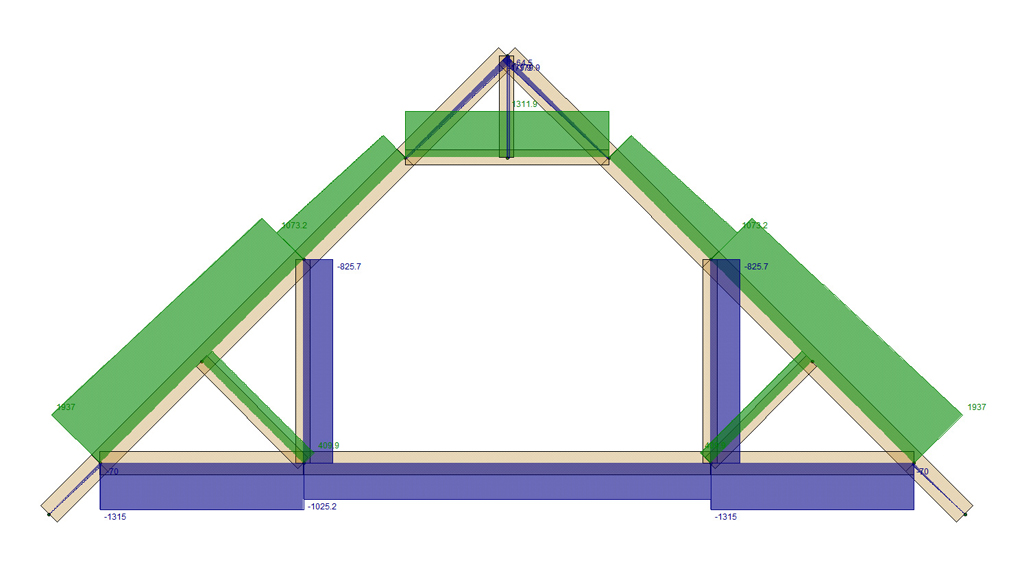
Axial Diagram:
This diagram shows the axial forces in the members of the truss. Segments shaded blue are member in tension, while those shaded green are in compression.
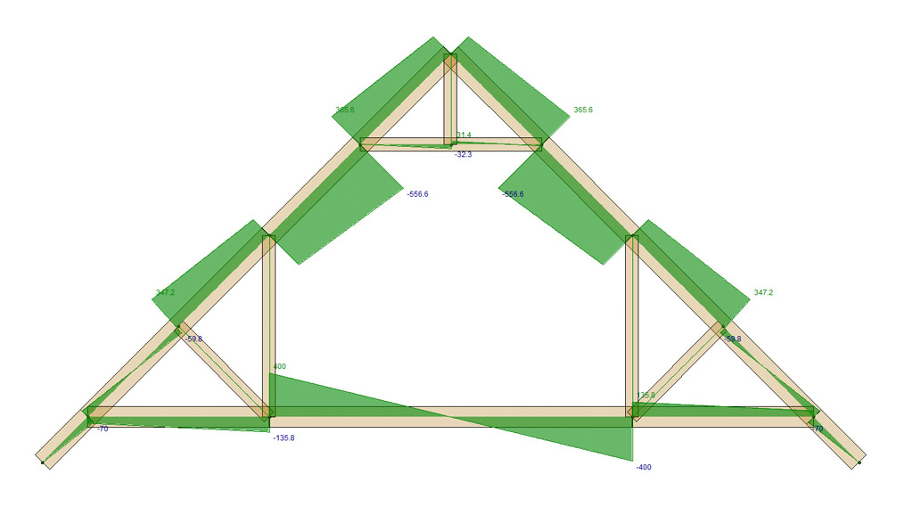
Shear Diagram:
This diagram shows the shear forces in the members of the truss.
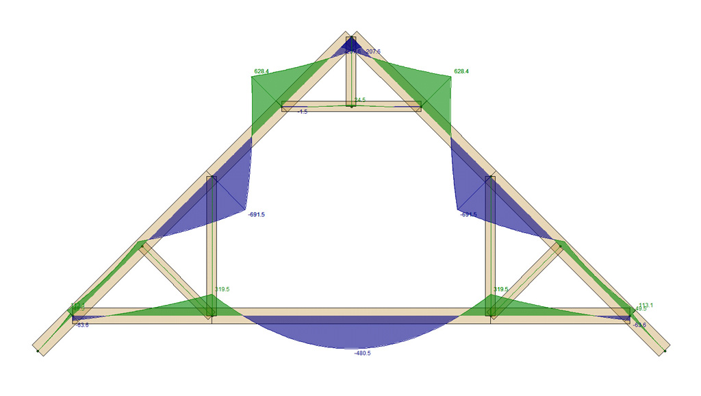
Moment Diagram:
This diagram shows the bending moments in the members of the truss. Notice the large bending moments at the midspan of the bottom chord. Typically the bottom chord is considerably deeper that the rest of the truss members to resist this bending and also to prevent a "bouncy" floor.Since the joints of the webs of the truss were modeled as "pin jointed" there is virtually no bending in these web members, except for the ceiling web which has an applied load. In this model the heel and peak joint were modeled as a rigid joints hence the moments are non-zero at these locations. Alternatively these joints could also be modeled as semi-rigid or pinned.
Conclusions
Fully analyzing an attic truss is a complicated and daunting prospect. The diagrams shown illustrate one of possibly many load cases require to fully engineer such a truss. The hours required to create all of these load cases and scenarios is usually beyond what most consumers are willing to pay for such a product and therefore the industry wide automation of this process.
Most MPC wood trusses manufactured throughout the world are designed and engineered with specialized software that fully automates the engineering of both members and plates. Unfortunately, this software is not available to engineers, design professionals or consumers, so when specific design or engineering questions arise the tedious methods described above must be employed. Even if the engineer does generate all of the possible load cases within a program such as RISA3D and manages to adequately check all of the wood members according to the current NDS there is still the question of the metal plates and their associated engineering per the ANSI/TPI 1-2014 standard. It is my professional opinion that a software solution that targets those other than truss manufacturing companies should also be made available to design professionals and possibly even to the general public.
As such no product currently exists and it has been my objective to begin filling this need with the development of the Truss Designer and Truss Plugin.
If you have any questions about attic trusses or the analysis of trusses in general please contact us.