|
DRAW ROOF TRUSS: COMMON TRUSSES
Common Trusses
Overview
The common or pitched truss type, characterized by its symetric triangular shape, is the most commonly used truss type for roof construction. Common trusses are named according to their internal web configuration as shown below:
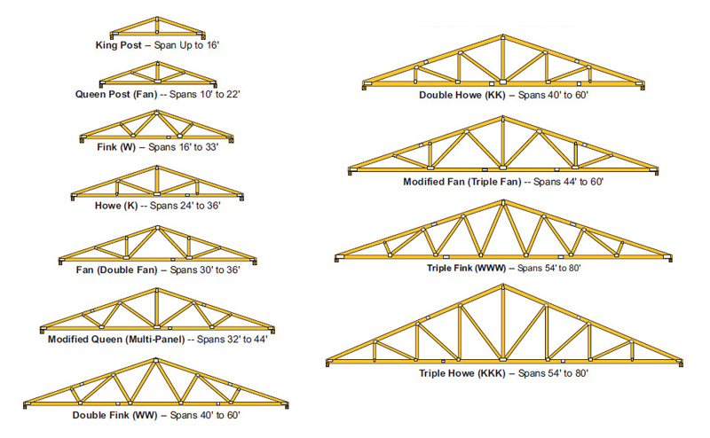
The chord sizes and web configurations are determined by span, load and truss spacing. There is a practical limit to the allowable length of any truss chord or web member, hence larger spans typically require more panels and webs.
Truss Terms
The terms below are typically used to describe the various parts of a metal plate connected wood truss:

The truss pitch, span, heel height, overall height, overhang and web configuration depend on your specific design conditions. Most of these parameters can be defined within the plugin. Specific details such as metal plates and location of chord splices are not represented by the plugin output (geometry).
Drawing Trusses
Once "Common" has been selected as the Roof Truss Family the user selects three points which define the bounding rectangle of the truss assembly:

The distance between point (1) and point (2) determines the out-to-out span of the truss. The distance between point (2) and point (3) determines the length of the truss assembly or building.
Once the bounding rectangle is defined the geometry menu will pop up and display the following parameters and options:
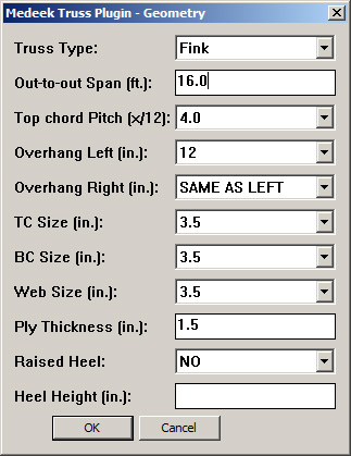
Definitions for these design parameters and options are explained below:
Truss Type This item lists the common truss types that can be modeled within the plugin. The default is a fink type truss.Out-to-out Span Outside to outside of bearing walls that truss is spanning. This span is typically given in feet or metres.Top Chord Pitch Vertical rise divided by horizontal run. This number is typically expressed as a ratio of incline (in.) to each 12 inches of run. For example 3:12, 4:12, 5:12 and so on. The plugin limits the roof pitch from 2.5:12 to 12:12 for imperial units and allows the slope of the roof to be entered in as degrees with metric units.Overhang Distance the truss projects beyond the bearing wall (outside) in inches/mm. The overhang can be within the range of 0 to 48 inches for imperial units. Left and right overhangs can be set indepedently of each other.TC Size Sets the depth of the top chord members of the truss in inches/mm. Values are limited to nominal lumber sizes for imperial units.BC Size Sets the depth of the bottom chord members of the truss in inches/mm. Values are limited to nominal lumber sizes for imperial units.Web Size Sets the depth of the web members of the truss in inches/mm. Values are limited to nominal lumber sizes for imperial units.Ply Thickness Sets the width of the truss members in inches/mm. Values are not limited and the default is 1.5 inches for 2x lumber in imperial units.Raised Heel This option allows a raised or energy heel truss. Default value is "NO". Depending on the heel height raised heel trusses will require a wedge, slider or vertical web with strut. Trusses without raised heels will have a standard butt cut of 1/4 inches.Heel Height Sets the heel height of the truss in inches/mm if raised heel option in enabled otherwise this value is ignored. Default value is 12 inches if raised heel option enabled and no heel height is entered (imperial units).
A second parameter menu will then pop up and display the following parameters and options:
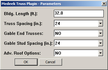
Definitions for these design parameters and options are explained below:
Bldg. Length The length of the truss assembly (or length of the building the truss assembly is spanning). This length is typically given in feet or metresTruss Spacing On center distance between trusses in inches/mm.Gable End Trusses This option enables gable end trusses at the both ends of the truss assembly.Gable Stud Spacing Sets the on center spacing between studs (inches/mm) in the gable end trusses if this option is enabled.Adv. Roof Options Enables advanced options for this truss assembly, see advanced options below. Default value is "NO".
If advanced roof options is not enabled the truss assembly will be generated and the resulting geometry will resemble the example given below:
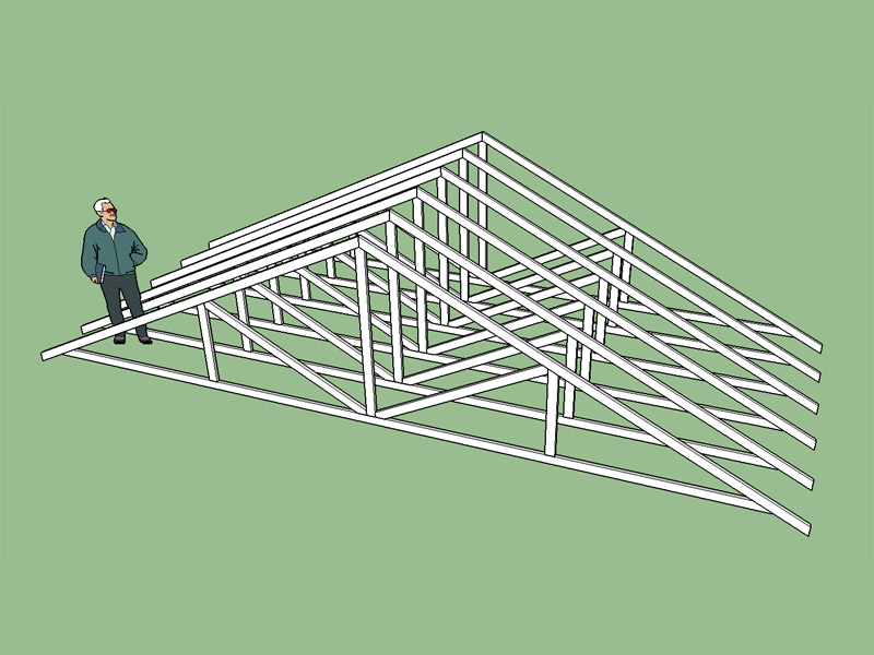
Each individual member (chords, webs, sliders, wedges etc...) of the truss is modeled as a group with the entire truss forming a component having a unique name (ie. FINK_TRUSS_24_20151019123215). The Array of trusses is created by invoking multiple instances of this truss component. This allows for modifications to all the trusses in an array by simply modifying one truss. Creating each member of the truss as a group allows modificatons or deletions to each member without affecting the rest of the truss geometry. Additionally each truss assembly is grouped in order to facilitate future adjustments to the truss assembly as a whole.
Advanced Options
If the advanced roof option(s) is enabled in the second menu a third menu will pop up, prior to the creation of geometry, and display the following parameters and options:

Definitions for these advanced parameters and options are explained below:
Sheathing This option enables roof sheathing/cladding for the top of the roof. Default value is "NO". Perimeter of sheathing is flush with rake and fascia.Sheathing Thickness Sets the thickness of the sheathing in inches/mm. Standard plywood/OSB sizes are given for imperial units.Sub-Fascia This option enables sub-fascia at the tails of trusses. Default value is "YES".Sub-Fascia Type Sets the configuration of the sub-fascia. The sub-fascia options are DROP, FLUSH or BEVEL. This option will also affect the sheathing perimeter location, if enabled.Sub-Fascia Width Sets the thickness or width of the sub-fascia in inches/mm. Values are limited to nominal lumber sizes for imperial units.Sub-Fascia Depth Sets the depth of the sub-fascia in inches/mm. Values are limited to nominal lumber sizes for imperial units.Rakeboard This option enables a rake board (barge rafter/fly rafter) at the gable ends of the truss assembly. Default value is "YES".Gable Overhang Sets the overhang of the rakeboard in inches/mmRake Board Width Sets the thickness or width of the rakeboard in inches/mm. Values are limited to nominal lumber sizes for imperial units.Rake Board Depth Sets the depth of the rakeboard in inches/mm. Values are limited to nominal lumber sizes for imperial units.Outlookers This option enables outlookers at the gable ends of the truss assembly. Default value is "YES".Spacing Sets the on center spacing between outlookers (inches/mm) if the outlooker option is enabled.Size Sets the nominal size of the outlookers. Default is "2X4" lumber for imperial units.Structural This option determines whether outlookers are structural or non-structural. Default value is "NO".Orientation This option sets the orientation of the outlookers. Default value is "HORIZONTAL".Outlookers @ Peak The option creates an additional set of outlookers at the peak of the roof.Heel Blocking This option enables heel blocking/bird blocking at the heel of the truss. Default value is "NO". Currently this option is inactive/under construction.
Orientation This option sets the orientation of the heel blocking. Default value is "VERTICAL". Currently this option is inactive/under construction.
A typical common truss roof with advanced options enabled will resemble the example given below (sheathing has been disabled for clarity):
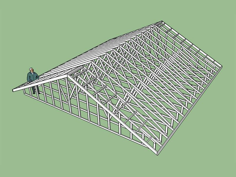
In this example a raised heel fink truss creates the profile of the roof. Note the use of structural outlookers (oriented vertically), with a additional outlookers at the peak of the roof. Also note that the structural outlookers alter the gable end trusses and create a dropped top chord configuration. Both sub-fascia and rakeboard are shown.
Common Trusses
Questions? Call 1-425-652-4188 or email nathan@medeek.com
|