Subject
Customer
Location
Job No.
Engr.
Rev.
Date
Page

Beam Design

1. Beam Data

Load Type: Single Point Load  
Support: Simple Beam  
Beam Type: Sawn Lumber  
Species: Spruce-Pine-Fir  
Grade: SPF No.2  
Size: 4 x 6  
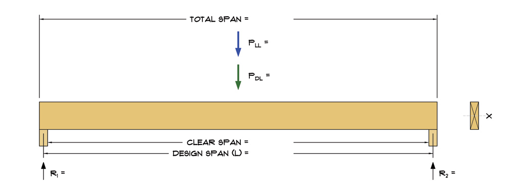
Design Span (L): 3.83 ft.
Clear Span: 3.67 ft.
Total Span: 4.00 ft.
Bearing (lb): 2 in.
Quantity (N): 1  

2. Design Loads

Live Load: 300 lbs
Dead Load: 75 lbs
Selfweight: 14.9 lbs
Dist. Selfweight: 3.89 plf
Total Weight: 15.6 lbs

3. Design Options

Lateral Support: braced
Defl. Limits: 180|120
Load Duration: 1.15
Exposure: dry
Temperature: T <= 100°F
Orientation: Vertical
Incised Lumber: No
Rep. Members: No

4. Design Assumptions and Notes

Code Standard: IBC 2015, NDS 2015
Bending Stress: Parallel to Grain
Notes:

5. Adjustment Factors


Factor Description Fb Ft Fv Fc Fc⊥ E/Emin
CD Load Duration Factor 1.15 1.15 1.15 1.15 - -
CM Wet Service Factor 1b 1 1 1c 1 1
Ct Temperature Factor 1 1 1 1 1 1
CL Beam Stability Factor 1 - - - - -
CF Size Factor 1.3 1.3 - 1.1 - -
Cfu Flat Use Factor 1.05d - - - - -
Ci Incising Factor 1 1 1 1 1 1
Cr Repetitive Member Factor 1 - - - - -
                  a) Adjustment factors per AWC NDS 2015 and NDS 2015 Supplement.
                  b) When (Fb)(CF) ≤ 1,150 psi, CM = 1.0.
                  c) When (Fc)(CF) ≤ 750 psi, CM = 1.0.
                  d) Only applies when sawn lumber or glulam beams are loaded in bending about the y-y axis.
Beam Design 2020A292
N. Wilkerson MEDEEK ENGINEERING INC.
3050 State Route 109 Copalis Beach, WA 98535
ph. (425) 741-5555    www.medeek.com
-
12/21/2020 1
Subject
Customer
Location
Job No.
Engr.
Rev.
Date
Page

6. Beam Calculations

Determine reference design values, sectional properties and self weight of beam:

A = b x d

 , 

 , 

where:

b = Breadth of rectangular beam in bending (in.)
d = Depth of rectangular beam in bending (in.)
A = Cross sectional area of beam (in.2)
Sx = Section modulus about the X-X axis (in.3)
Sy = Section modulus about the Y-Y axis (in.3)
Ix = Moment of inertia about the X-X axis (in.4)
Iy = Moment of inertia about the Y-Y axis (in.4)

b = 3.500 in.
d = 5.500 in.
A = 3.500 x 5.500 = 19.25 in.2
Sx = (3.500)(5.500)2/6 = 17.65 in.3
Sy = (3.500)2(5.500)/6 = 11.23 in.3
Ix = (3.500)(5.500)3/12 = 48.53 in.4
Iy = (3.500)3(5.500)/12 = 19.65 in.4

Reference Design Values from Table 4A NDS Supplement (Reference Design Values for Visually Graded Dimension Lumber, 2" - 4" thick).

Species & Grade Fb Ft Fv Fc⊥ Fc E Emin G
SPF No.2 875 450 135 425 1150 1400000 510000 0.42

The following formula shall be used to determine the density of wood (lbs/ft3.  (NDS Supplement Sec. 3.1.3)


where:

ρw = Density of wood (lbs/ft3
G = Specific gravity of wood (dimensionless)
m.c. = Moisture content of wood (percentile)

G = 0.42
m.c. = 19 %   (Max. moisture content at dry service conditions)
Beam Design 2020A292
N. Wilkerson MEDEEK ENGINEERING INC.
3050 State Route 109 Copalis Beach, WA 98535
ph. (425) 741-5555    www.medeek.com
-
12/21/2020 2
Subject
Customer
Location
Job No.
Engr.
Rev.
Date
Page

= 29.10 lbs/ft3

Volumetotal = N[A x (L + lb)] = 1 x [19.25 x (46.00 + 2)] x (12 in./ft.)3 = 0.53 ft3
Volumespan = N[A x L] = 1 x [19.25 x 46.00] x (12 in./ft.)3 = 0.51 ft3

Total Weight (WT) = ρw x Volumetotal = 29.10 x 0.53 = 15.6 lbs
Self Weight (WS) = ρw x Volumespan = 29.10 x 0.51 = 14.9 lbs

Distributed Self Weight (ws) = = 3.89 plf


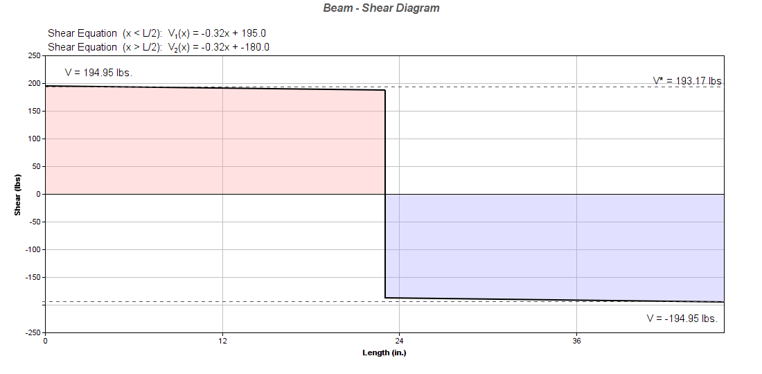
Load, Shear and Moment Diagrams:

300 lbs
75 lbs
ws = 3.89 plf
3.83 ft.
3.67 ft.
4.00 ft.
195.28 lbs
195.28 lbs


Beam Design 2020A292
N. Wilkerson MEDEEK ENGINEERING INC.
3050 State Route 109 Copalis Beach, WA 98535
ph. (425) 741-5555    www.medeek.com
-
12/21/2020 3
Subject
Customer
Location
Job No.
Engr.
Rev.
Date
Page


1.) Bending:

Members subject to bending stresses shall be proportioned so that the actual bending stress or moment shall not exceed the adjusted bending design value:

fb ≤ Fb'  (NDS Sec. 3.3.1)

where:

fb = M / S
Fb' = Fb(CD)(CM)(Ct)(CL)(CF)(Ci)(Cr)

Beam is braced laterally along its compression edge. Laterial stability is not a consideration:

CL = Beam Stability Factor = 1.0

Fbx' = (875)(1.15)(1)(1)(1)(1.3)(1)(1) = 1308.1 psi

fb = = 249.2 psi

 fb = 249.2 psi < Fbx' = 1308.1 psi  (CSI = 0.19)   ➜  OK


Beam Design 2020A292
N. Wilkerson MEDEEK ENGINEERING INC.
3050 State Route 109 Copalis Beach, WA 98535
ph. (425) 741-5555    www.medeek.com
-
12/21/2020 4
Subject
Customer
Location
Job No.
Engr.
Rev.
Date
Page

2.) Shear:

Members subject to shear stresses shall be proportioned so that the actual shear stress parallel to grain or shear force at any cross section of the bending member shall not exceed the adjusted shear design value:

fv ≤ Fv'  (NDS Sec. 3.4.1)

where:

fv =

Fv' = Fv(CD)(CM)(Ct)(Ci)

Fvx' = (135)(1.15)(1)(1)(1) = 155.25 psi

Shear Reduction: For beams supported by full bearing on one surface and loads applied to the opposite surface, uniformly distributed loads within a distance, d, from supports equal to the depth of the bending member shall be pemitted to be ignored. For beams supported by full bearing on one surface and loads applied to the opposite surface, concentrated loads within a distance equal to the depth of the bending member from supports shall be permitted to be multiplied by x/d where x is the distance from the beam support face to the load. See NDS 2015, Figure 3C.

fv* = = 15.05 psi

 fv* = 15.05 psi < Fvx' = 155.25 psi  (CSI = 0.10)   ➜  OK


No Reduction in Shear (conservative):

fv = = 15.19 psi

 fv = 15.19 psi < Fvx' = 155.25 psi  (CSI = 0.10)   ➜  OK


3.) Deflection:

Bending deflections calculated per standard method of engineering mechanics for live load and total load:

LL Allowable: L/180
TL Allowable: L/120

Ex' = Ex(CM)(Ct)(Ci) = 1400000(1)(1)(1) = 1400000 psi
Beam Design 2020A292
N. Wilkerson MEDEEK ENGINEERING INC.
3050 State Route 109 Copalis Beach, WA 98535
ph. (425) 741-5555    www.medeek.com
-
12/21/2020 5
Subject
Customer
Location
Job No.
Engr.
Rev.
Date
Page

ΔLL =   =   = 0.01 in.

(L/d)LL = 46.00 / 0.01 = 5138

 ΔLL = 0.01 in = L/5138 < L/180   ➜  OK


ΔTL =   =   = 0.01 in.

(L/d)TL = 46.00 / 0.01 = 4011

 ΔTL = 0.01 in = L/4011 < L/120   ➜  OK


4.) Bearing:

Members subject to bearing stresses perpendicular to the grain shall be proportioned so that the actual compressive stress perpendicular to grain shall be based on the net bearing area and shall not exceed the adjusted compression design value perpendicular to grain:

fc⊥ ≤ Fc⊥'  (NDS Sec. 3.10.2)

where:

fc⊥ =

Fc⊥' = Fc⊥(CM)(Ct)(Ci)

Fc⊥x' = (425)(1)(1)(1) = 425.00 psi

Ab = b x lb = 3.5 x 2 = 7.00 in2

fc⊥ = = 27.9 psi

 fc⊥ = 27.9 psi < Fc⊥x' = 425.00 psi  (CSI = 0.07)   ➜  OK


*Disclaimer: The calculations produced herein are for initial design and estimating purposes only. The calculations and drawings presented do not constitute a fully engineered design. All of the potential load cases required to fully design an actual structure may not be provided by this calculator. For the design of an actual structure, a registered and licensed professional should be consulted as per IRC 2012 Sec. R802.10.2 and designed according to the minimum requirements of ASCE 7-10. The beam calculations provided by this online tool are for educational and illustrative purposes only. Medeek Design assumes no liability or loss for any designs presented and does not guarantee fitness for use.
Beam Design 2020A292
N. Wilkerson MEDEEK ENGINEERING INC.
3050 State Route 109 Copalis Beach, WA 98535
ph. (425) 741-5555    www.medeek.com
-
12/21/2020 6