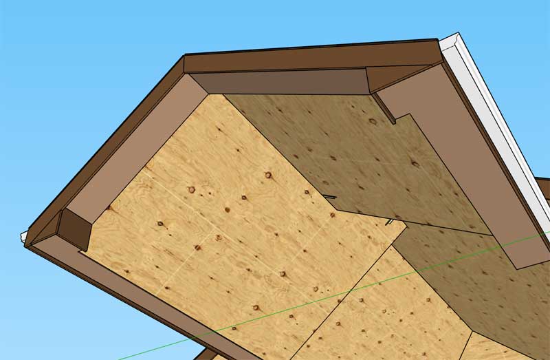
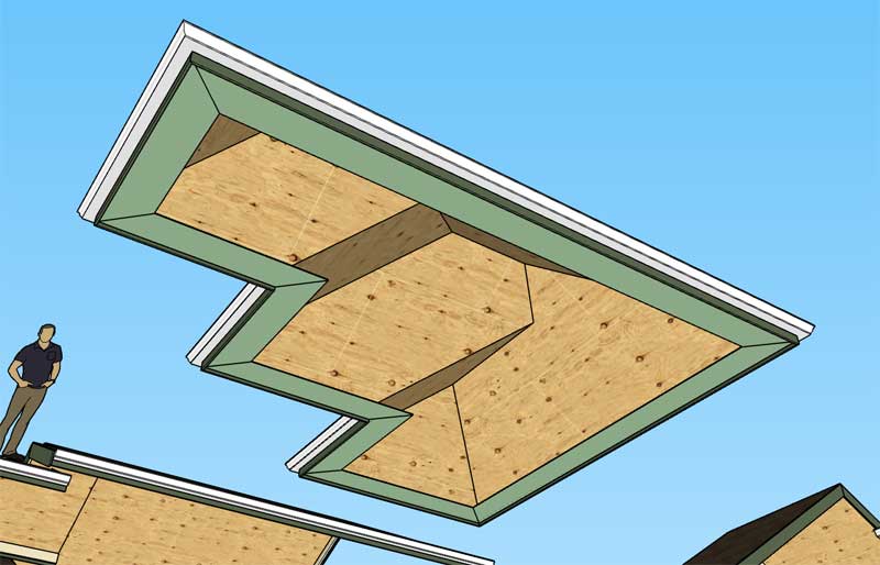
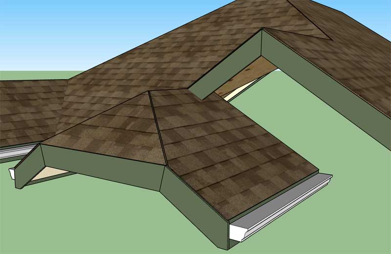
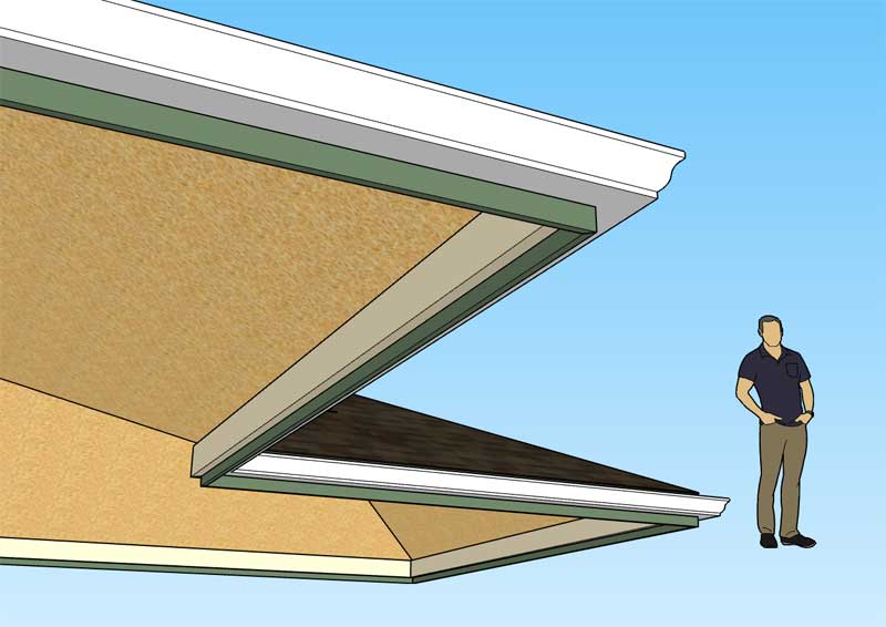
News:

SMF - Just Installed!

Main Menu
Menu

Show posts

This section allows you to view all posts made by this member. Note that you can only see posts made in areas you currently have access to.

Show posts Menu

Messages - Medeek

#1336
Version 2.3.4 - 04.24.2019
- Enabled the "Edit Roof Assembly" function for gable and hip rafter roofs (imperial and metric units).
- Corrected an issue with H2.5A hurricane ties when utilized with raised heel trusses.


This is a fairly substantial upgrade for the plugin and now gives the user the ability to edit stick framed roofs.  Previously only certain truss roofs could be edited. 

I still need to enable editing for the other rafter roof types (shed roofs, I-Joist, rafter roofs with glulam beams etc...), but at least I've now got the two most common roof types with full parametrics enabled.
#1337
Looks like the listing is finally live in the Extension Warehouse:

https://extensions.sketchup.com/en/content/medeek-wall-plugin-1
#1338
When I originally enable hurricane (uplift) ties for the trusses I failed to check to see how things looked with a raised heel when the H2.5A (simpson) tie was used. 

In this particular case the tie needs to be flipped around so that it is facing towards the interior rather than the exterior.  I've made the correction and added the logic into the code.  I will release the fix with the next version:

#1339
Since adding the symbols legend I've had a number of requests for a tool to draw a schedule (similar to how I am drawing the legend).

Now that I've got a fairly solid routine for pulling the electrical data (I will use much of this same code for the estimating tool) it isn't too big of a leap to draw a schedule.

My question is what information do you need or want in this schedule, how do you want it laid out?  Every device listed with its parameters or do I group like devices?

Please give feedback in this regard.  Also feel free to send me any sample electrical schedules that I can utilize as references.

If I know what I want to output I can probably knock this out in 2-3 hours, most of the underlying code is already in place.
#1340
Version 2.3.3 - 04.17.2019
- Enabled the "Edit Truss Assembly" function for attic trusses (imperial units only).
- Improved formatting of all HTML edit menus: Common, Monopitch, Scissor, Attic.

#1341

Tutorial 3:  Electrical Symbols Legend


#1342
Version 2.3.2 - 04.15.2019
- Enabled the "Edit Truss Assembly" function for all scissor trusses (imperial and metric units).
#1343
Version 1.0.6 - 04.15.2019
- Added additional NEMA 240V receptacles into the Outlet module: NEMA 6-30R, NEMA 6-50R.

These additional receptacles (and symbols) were per customer request.


#1344
For those that are interested I will explain how the new "Draw Legend" tool works under the hood.

First the plugin finds all of the groups in the model (active_entities, if no group or component is open for editing then this will be the same as entities at the root of the model).

It then checks inside each of these groups and identifies the electrical groups that belong to the plugin (based on the group instance name).  Once it has collected up all of the electrical groups in the model it then divides them into their appropriate categories:  Outlets, Switches, Light etc...

It then examines each sub-category and dives into the attributes library for each electrical device (group).  The attributes library tells it what 2D symbol is associated with that particular device.  It then creates a  new list of symbols to draw for the legend for each category at the same time discarding or preventing duplicates.

The symbols shown in the legend are drawn, for the most part, using the same methods as the symbols drawn for the actual devices however some of them have been altered slightly in order to customize them specifically for the legend.

As you can see there is quite a bit going on under the hood.  When a model gets large with hundreds of walls and possibly hundreds of electrical components generating the legend may take up to 30 seconds.
#1345
I think the real power in this plugin is not the ability to insert 3D components into your model, technically you don't even need a plugin to do this, just a bunch of pre-configured components (.skp files).  The real strength is the automation of the 2D symbols and the parametrics of the plugin (allowing you to swap out devices types, colors, height and rotation).  Now with the addition of a parametric symbols legend it automates yet another tedious task.

I'm fairly happy with the way the legend has come out but for future work I may include a parameter in the global settings which allows the user to enable sub-titles (divides the legend into logical sections:  outlets, switches, lights, etc...) as well as specify the number of columns that legend should be divided into, this becomes more of an issue when there are a lot of electrical symbols to display.

I think some people would argue that I go too deep with my plugins (too many settings, parameters, options etc...)  I would agree that if possible simple is often better.  The goal is to make everything as simple as possible, but not simpler.

On the flip side the addition of more options and parameters increases the amount of data or information that model contains and hence makes it more useful (BIM).  Options also allow the user to further customize their workflow with the plugin and tailor it specifically to their needs.  Many of the options I have added have been directly requested by users of the plugins
#1346
Version 1.0.5 - 04.12.2019
- Added the "Draw Legend" function to the secondary toolbar.
- Enabled the ability to automatically create an electrical symbols legend for all electrical devices within the model.


After working my way down through the list of possible symbols I'm surprised to see that there are so many and the legend can get quite large. 
#1347


Outlets, Switches, Low Voltage and Load Centers.

I still need to add in lights, safety devices, Heaters and Vents.
#1348
First look at the electrical symbols legend generated by the plugin:


The secondary toolbar has the icon for generating the legend:


The legend is parametric so every time you click the legend icon/tool it regenerates the legend based on what electrical devices are present in the model.  You can also move (x, y or z) or rotate the legend and it will retain these new coordinates when it is regenerated. 

Initially the legend is drawn at the origin but can be positioned at any location (and retained) by the user using SketchUp's native move or rotate tools.

The overall size of the legend and its text and symbol size is driven by the parameter in the global settings, as is the font of the text which will match the font used by the electrical symbols in the model.

It also appears that you can use SketchUp's native scale tool to scale the legend and it will also retain this setting when regenerated.
#1349
Version 1.0.4e - 04.10.2019
- Added an advanced option for wall mounted light fixtures to display the device height with the 2D symbol.


I also resolved a minor bug with the placement of wall mounted light fixtures so I highly recommend upgrading to this latest release.
#1350
Version 1.0.4d - 04.09.2019
- Added an advanced option for switches and low voltage outlets to display the device height with the 2D symbol.