News:

SMF - Just Installed!

Main Menu
Menu

Show posts

This section allows you to view all posts made by this member. Note that you can only see posts made in areas you currently have access to.

Show posts Menu

Messages - Medeek

#766
An example of point loads with Load Labels and Magnitudes turned on:

#767
The loads and supports will be on the Eng layer, annotations will be on Eng2 and warning graphics will be on Eng3.

Here is an example of some point loads applied to a timber beam, now I just need to setup annotations:


The different color arrowheads indicate one of the six load types (Dead, Live Floor, Live Roof, Wind, Snow, Seismic).  The colors assigned to each load type will be able to be customized in the global settings.  The size of the arrowheads will also be customizeable.

Regenerating the beam geometry will not regen the loads, there will be separate context menu item (right click the beam) to regen the engineering loads/supports.
#768
MK Electric has a very extensive product line. There is also the MK Grid Plus line which is similar to the Leviton QuickPort system however it is primarily for switches not low voltage ports:

https://www.mkelectric.com/Documents/English/EN%20MK%20Catalogue/Grid%20Plus.pdf
#769
In the global settings there will be a new parameter for choosing the electrical standard.  The default standard will be NEMA (North America) with a new option for the BS (British Standard).

When you enable the British standard the usual toolbars will be the same however you will also get a third toolbar for British standard specific outlets and switches (and in the future possibly other specific items).  The regular NEMA switches and outlets will still be available with the main toolbar so in case the user wants a mixed installation of NEMA and BS components.  I may change this in the future depending on customer feedback.

The initial UK toolbar will be:


I wish the Union Jack displayed with a bit more clarity but it is hard to get a lot of detail when the icons are as small as they are.
#770
Version 1.5.8b - 08.02.2020
- Added a semi-transparent polygon fill to the draw wall tool wireframe.
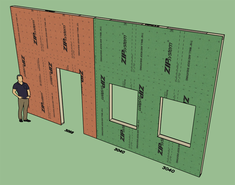
- Added an option for vertical ZIP Systems© 7/16" and 1/2" wall sheathing materials.


View model here:

https://3dwarehouse.sketchup.com/model/752a6027-fd47-42da-88e7-245eed5a5691/Zip-System-Wall-Sheathing-Vert
#771
Version 1.5.8 - 08.01.2020
- Fixed a bug with all wall assemblies when auto-assigment of materials is turned off in the global settings.
#772
Version 2.7.7 - 07.31.2020
- Fixed a bug with all assemblies when auto-assignment of materials is turned off in the global settings.
#773
Still working on how best to graphically represent the various loads and supports but this a bit of a preview of how it will go:

#774
Merging this topic with the previous structural plugin topic.
#775
When you click on the "Draw Load/Support" icon of the toolbar you will be presented with this matrix menu:

#776
With respect to who will use this module, I actually do think a lot of architects and designers would find use for it even if they are unable to "stamp" their design as "engineered". There would be many situations where a designer would want to get a reasonably ballpark idea on how big a beam or header needs to be. Unless there are complex loading situations at play, assigning some basic loads and supports to a beam is usually not rocket science. However, as always it is garbage in, garbage out. Obviously the user needs to have some understanding of the correct site specific loads in order to get the correct answers.

That being said, my primary audience for this plugin is residential structural engineers (like myself) who are wanting to quickly apply loads to a design and push out a report with minimal effort. I still have a long way to go with all of this but I am definitely opening a new can or worms with this one, let's see where we can take it in the next few months.

I think I am entering uncharted territory with this new development. To my knowledge there does not exist a comprehensive software that combines architectural design with engineering, that is my goal with integrating this new engineering module/extension with the mdkBIM suite.
#777
This will be a separate extension that will be integrated with the other extensions in the mdkBIM bundle. It does not need to be installed with the mdkBIM bundle and is completely optional. However, it is not really a stand alone extension since it can only be used with geometry drawn by other Medeek extensions.

After giving it some additional thought I think it would be good to decouple this extension to the extent that even if for example the Wall plugin is not installed the user could install the engineering extension and still apply loads/support and analyze a given beam. However they would be unable to modify the beam as drawn (ie. size, depth, length) unless the Wall plugin was installed.

In the Account Manager its icon will be:

#779
I have been contacted by SketchUp (Educational Programs Coordinator) with regards to using SketchUp for electrical work.  They are looking for some examples of recent work to share with the IBEW and ETA (electrical union) to showcase the use of SketchUp in the design and layout of electrical systems.

I am not an electrical contractor so I don't have any actual real life case studies to share or demonstrate but I am hopeful that some of the current users of the electrical plugin might have some examples they are willing to share with the rest of the electrical community.

If you would be interested in sharing some of your work as a case study please contact me at nathan@medeek.com
#780
I was going to name the engineering module or plugin "Medeek Structural" however I've decided to change the name to "Medeek Engineering".

The plugin icon will now be:


The first toolbar I will add is the Beam Engineering Tools which will allow the user to add point loads, distributed loads and supports to beams drawn in the wall plugin: