News:

SMF - Just Installed!

Main Menu
Menu

Show posts

This section allows you to view all posts made by this member. Note that you can only see posts made in areas you currently have access to.

Show posts Menu

Messages - Medeek

#511
Version 2.1.6 - 06.07.2021
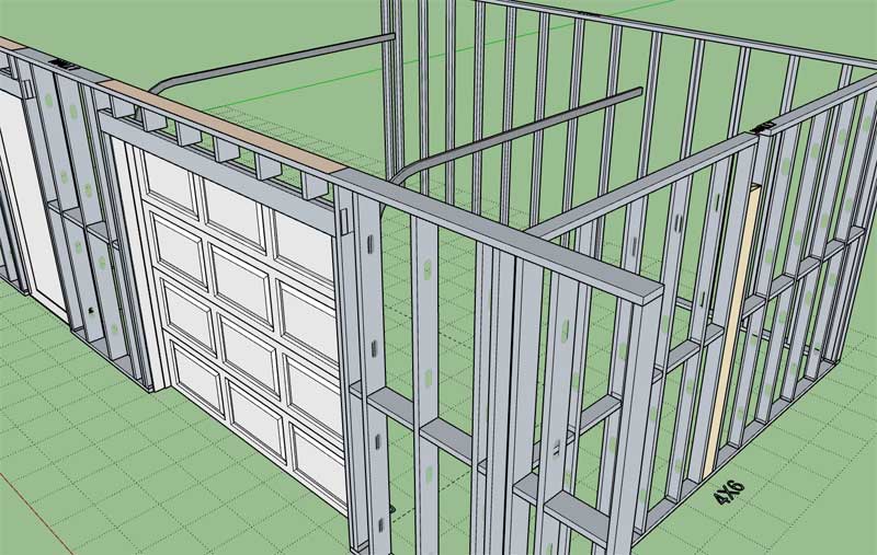
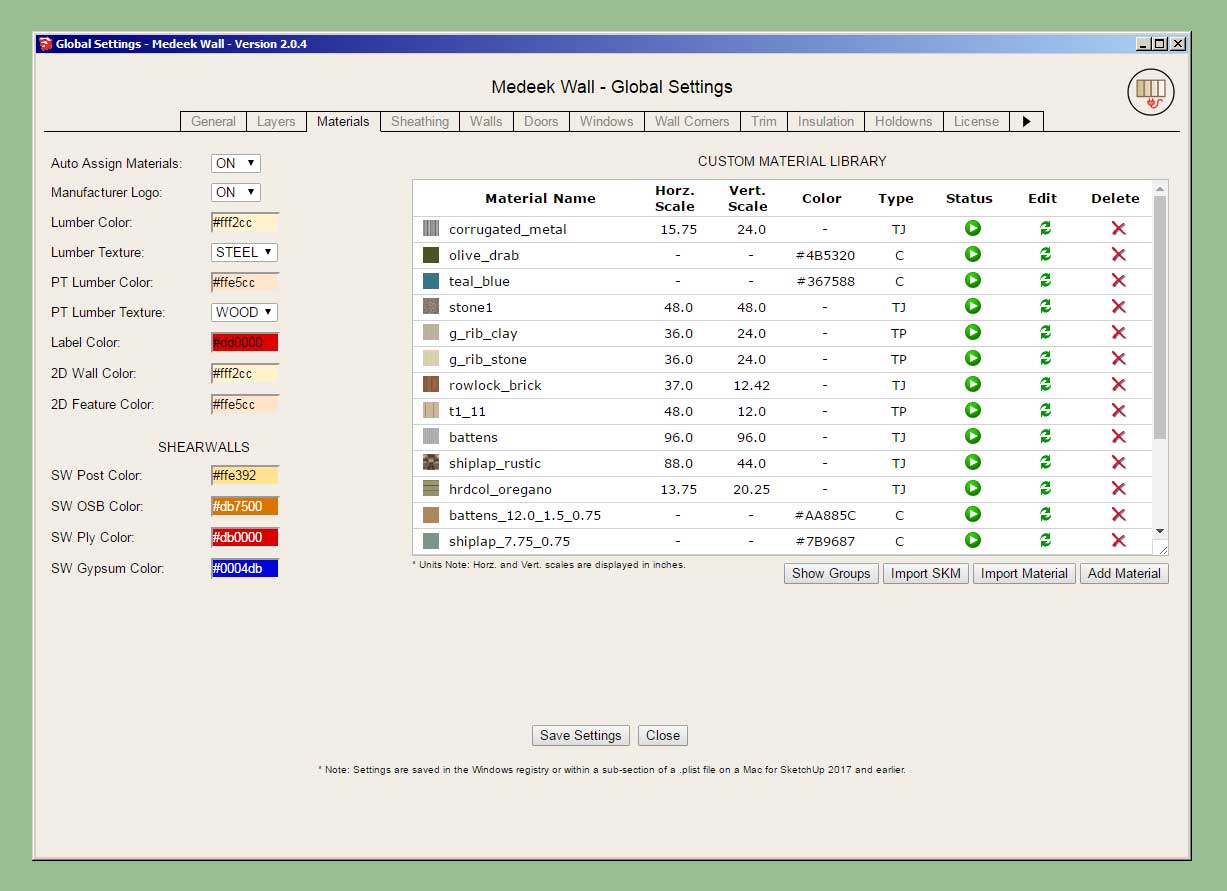
- Enabled an option for a steel framing (Cold Formed Steel) texture for lumber/studs in the global settings.


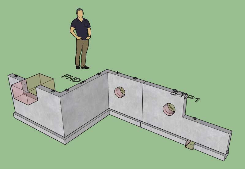
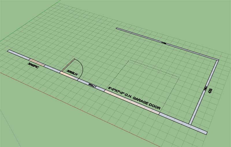
In the 2D mode the steel framed walls will appear a grey color as shown:


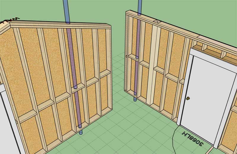
I was about to dive into the estimating module this morning but I received yet another email regarding steel framing.  This update only provides what I like to call a "cosmetic" steel framed wall.  All I am really doing is applying some textures (and hiding one face) to the otherwise standard wood studs so that they resemble a steel stud.  These are not proper steel framed walls in my opinion.

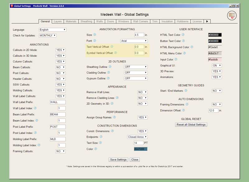
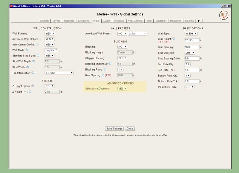
This option in the Materials tab of the global settings is somewhat experimental and I am sure further improvements can be made so please send me any feedback, but realize that dimensionally these are not "real" steel framed walls.  To take it to that level would probably involved creating an entirely new plugin devoted only to steel framing (CFS).

Please see model here:

https://3dwarehouse.sketchup.com/model/f1595258-f8b7-48cd-93c3-ff3cbf095b4f/CFS-Framing-1
#512
Version 2.1.5 - 06.06.2021
- Updated the Medeek Estimator to include lumber/member lengths in both feet-inches (fractional) and decimal inches when using imperial units.
- Further optimized and organized the Medeek Estimator code base in preparation for expansion of its functionality.

#513
Version 2.8.3 - 06.04.2021
- Added four additional parameters to the "User Interface" section of the General tab of the global settings. This allows the customization (colors) of the HTML menus and buttons.


This completes the user interface upgrade for all the major Medeek plugins.  The Truss, Foundation and Electrical plugins are now up to par with the Wall plugin.  Now on to bigger and better things, that task was very tedious but necessary.
#514
Version 1.7.2 - 06.03.2021
- Added four additional parameters to the "User Interface" section of the General tab of the global settings. This allows the customization (colors) of the HTML menus and buttons.
#515
Version 1.3.0 - 06.01.2021
- Added four additional parameters to the "User Interface" section of the General tab of the global settings. This allows the customization (colors) of the HTML menus and buttons.

#516
Version 1.2.9 - 05.30.2021
- Added an option for vertically offsetting text and symbols within the General tab of the Global Settings.
- Annotation text and symbols for outlets, switches, UK outlets and UK switches can be vertically offset a custom amount from the bottom of the wall.


The default placement was at the bottom of the framed wall, and the default offsets still are zero unless otherwise specified differently. However in most situations this resulted in Z-fighting with the subfloor and if a finished floor was modeled then the symbols and text would be buried within the finished floor or carpet (not visible). This option allows the user to customize the vertical placement to suit their particular needs.

This update was per customer request.
#517
Version 2.1.4 - 05.29.2021
- Added an option for vertically offsetting text and symbols within the General tab of the Global Settings.
- Annotation text and symbols for doors, windows, garage doors, columns, Simpson Strong walls, and shear walls can be vertically offset a custom amount from the bottom of the wall.


#518
Version 2.1.3 - 05.20.2021
- Fixed a bug with pocket doors when using the "No Frame" or "CMU" wall framing mode.
#519
Version 1.7.1 - 05.20.2021
- Fixed a bug with subbase and slab insulation options for slab-on-grade foundations.
#520
Version 2.1.2 - 05.10.2021
- Added logic into the add and draw menus to prevent users from using single and double quotes in preset names.
#521
Version 1.7.0b - 05.09.2021
- Components within foundations can also be made persistent and "subtractive" by naming the component instance to (subtract1, subtract2, subtract3, etc...)
#522
Version 2.1.1b - 05.09.2021
- Components within wall panels can also be made persistent and "subtractive" by naming the component instance to (subtract1, subtract2, subtract3, etc...)
#523
Version 1.7.0 - 05.09.2021
- Added an option for subtractive geometry into the General tab of the Global Settings.
- Sub-groups within foundations and footings can be made persistent and "subtractive" by naming these groups to (subtract1, subtract2, subtract3, etc...)


Interestingly the code to make this happen was staring me in the face for months.  I essentially took the "roof connections" complex roof module, changed up the logic slightly, simplified it, and arrived at this new feature/ability. 

Notice that the subtractive groups cut through the rebar as well as the concrete.  Certain other elements such as anchor bolts (groups within groups) are not removed.  I may need to give this some additional consideration.

I guess we need to make this new feature available with the Truss plugin as well now.
#524
First look at a hole cut using the new SUBTRACT keyword system:


Now I just need to set this up for the other various foundation types (ie. stemwall, stemwall steps, strip footings etc...)
#525
Version 2.1.1 - 05.09.2021
- Added an option for subtractive geometry into the Walls tab of the Global Settings.
- Sub-groups within wall panels can be made persistent and "subtractive" by naming these groups to (subtract1, subtract2, subtract3, etc...)


This is quite a major breakthrough for the wall plugin.  I've been trying to think of a way to enable (manual) customization of the wall geometry for quite some time, specifically subtractive modifications.  This system will now allow the user to achieve that goal.

Naming a group within the wall assembly to include the key word "CUSTOM" (case insensitive) will allow it to persist upon rebuild.

Naming a group within the wall assembly to include the key word "SUBTRACT" (case insensitive) will allow it to persist and boolean subtract from other groups within the assembly upon rebuild.

The subtractive group needs to be a valid solid for it to function correctly and its entity name needs to contain the key word "subtract" or "SUBTRACT".

What I like to do is create a special tag/layer for the subtraction geometry and then once I am done modifying or creating it I turn off the visibility of the layer/tag and only the holes or results in the wall geometry is shown.