News:

SMF - Just Installed!

Main Menu
Menu

Show posts

This section allows you to view all posts made by this member. Note that you can only see posts made in areas you currently have access to.

Show posts Menu

Messages - Medeek

#1831
Version 0.8.1 - 06.24.2018
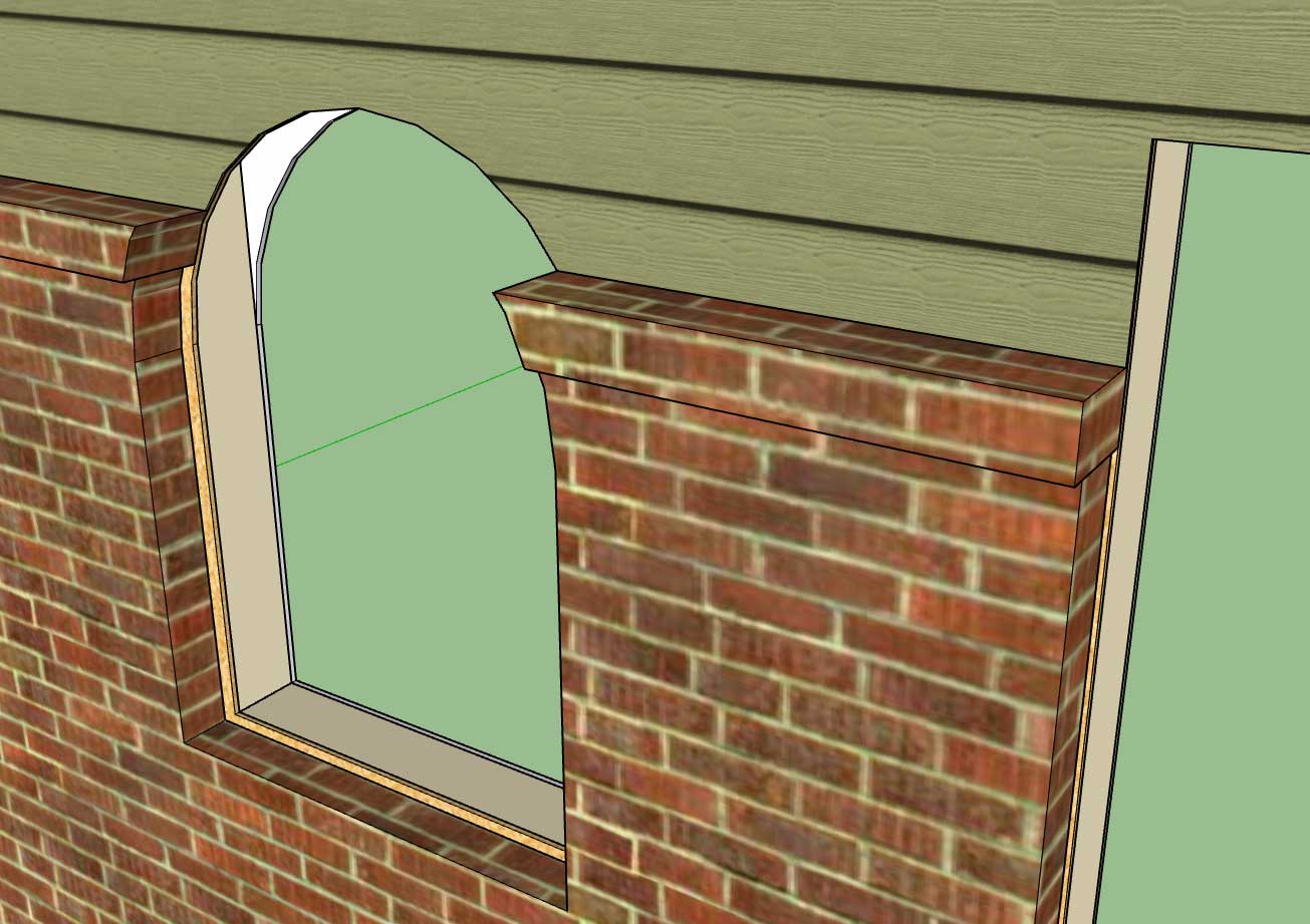
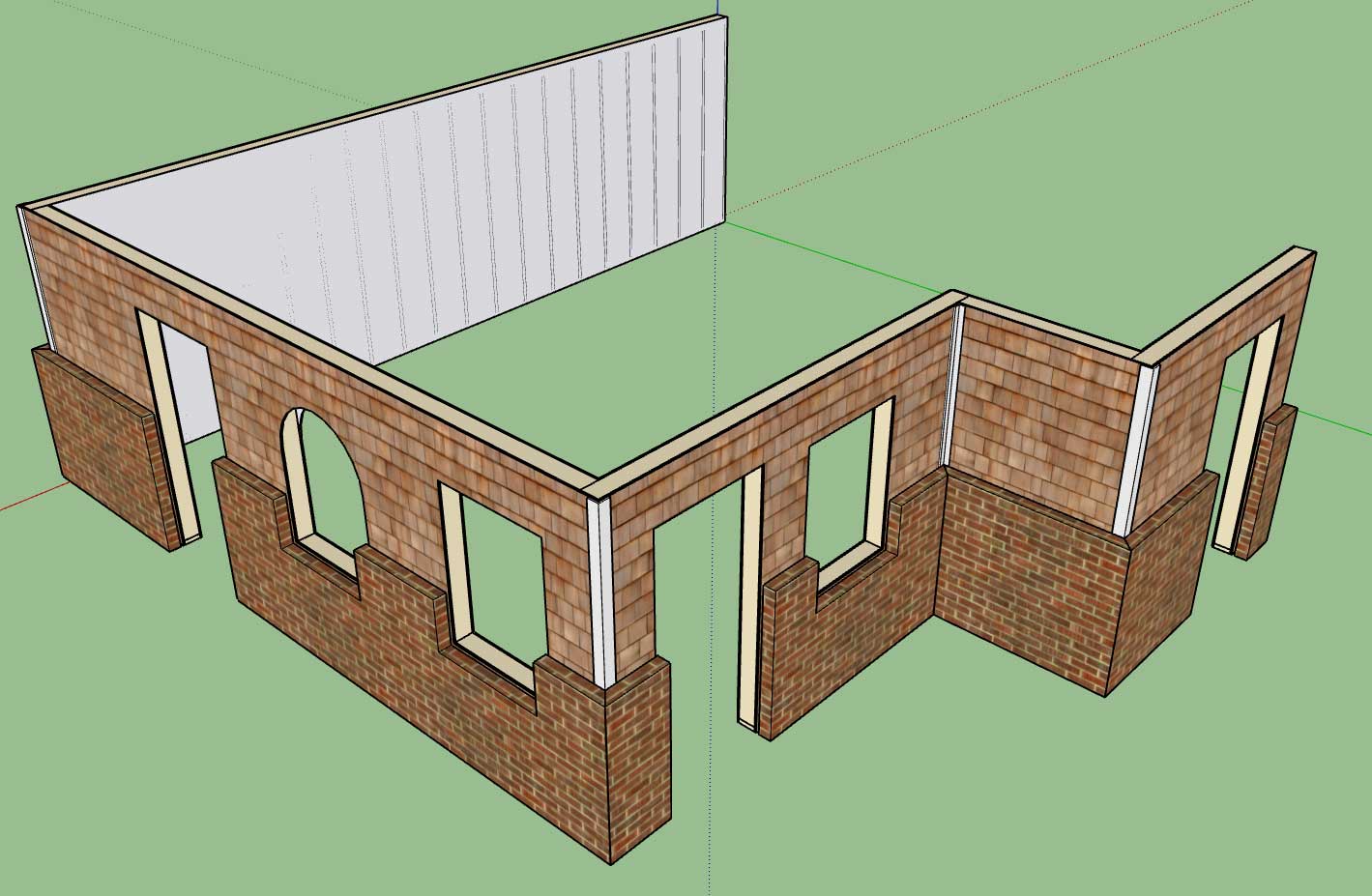
- Enabled exterior wainscoting for Ext-Int walls.
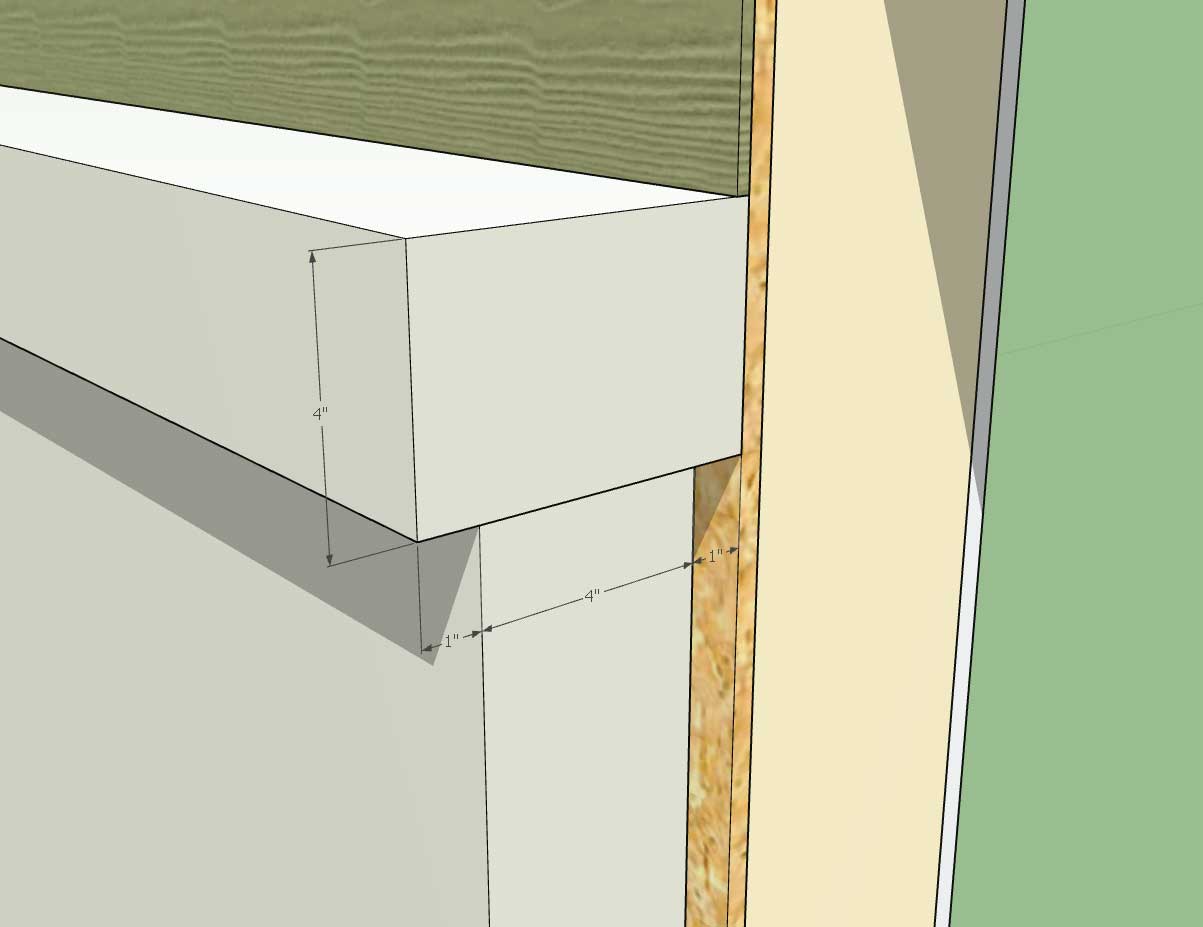
- Added additional parameters to the wainscot menu for window and wall ledges.
- Wainscot "cut" parameter added to the exterior trim menu in order to optionally cut corner trim at the wainscot height.


There are still a few more parameters and features that I feel needed to be added to this new feature class.  I am also willing to take suggestions on how to make this more useful.  Please give it a go and let me know what you think.

The wainscoting has also been added into the wall preset system.

Which brings me to a new idea I just had as I was applying presets to a few walls this morning.  The wall preset feature is quite handy but rather tedious to use if one wants to apply a specific preset to a number of walls (granted the wall grouping feature would come in handy here but that is still in development). 

What would be really handy is to have a "paintbrush" tool, where one could select any given wall panel and then all of its settings could then be transferred to any other wall panel with a single click of the mouse.  Essentially treating the initially selected wall as a "preset" and then applying that preset to any walls selected.  This would greatly speed up any changes one might need to make to a bunch of walls.  I also think it would useful to have the tool differentiate between exterior and interior wall types.  In other words if you initially select an exterior wall (ext-int) to copy those settings could not be applied to an interior wall (int-int).
#1832
Wainscot ledge:


The dimensions show the following parameters:

1.) Ledge Depth or Projection
2.) Ledge Height
3.) Wainscot Thickness
4.) Wainscot Air Gap

Notice that the ledge extends beyond the air gap to the sheathing or framing (if sheathing disabled).

Also note that wainscoting and ledge are able to bisect curved windows or doors as shown.

This additional feature is fairly complex so I am sure there may be some situations that I have not yet encountered and may be some cause for geometrical errors, only further testing will tell.
#1833
Some progress is being made:


I've got to work on the following to finish this up:

- Wainscot ledge (this is typical for brick [rowlock])
- Add in two additional parameters for trim above the wainscot (typical for stucco installations)
- Logic to trim back window and door exterior trim as well as corner trim.
- Logic to check for wainscoting with annotation placement.

Not sure what to do with the bottom of the window location where it cuts out the wainscoting (brick, cultured stone etc...)  this should also receive a ledge (ie. rowblock) as well.
#1834
Version 0.8.0b - 06.21.2018

- Added the ability to toggle between center, left or right positioning (by pressing the CTRL key) while drawing windows, doors, columns or SSWs.

This was a highly requested update and did not require any significant code changes.  I strongly suggest everyone upgrade to this latest release to take advantage of the convenience of being able to toggle the position of these elements, a small upgrade but a large functional increase.
#1835
The first thing you may notice with the SSW tool is that the current selection of sizes (widths and heights) of the pre-fab shearwalls is limited to 24" wide and between 8' and 12' in height.  I also do not have any metric sizes or manufacturers other than these two (Hardy Frame HFX (Mitek) and Simpson Strong-Tie).

I will roll out the full line of both manufacturers lines in the next few days however I have a few more smaller but hotter items that I would like to address first.

The first item is to allow the user the ability to toggle the placement of windows/doors/columns/SSWs from their center to left or right.  I'm considering using the SHIFT key to make this toggle unless there are any specific objections. 

Once I have this feature up and running I would like to make a tutorial video for both columns and SSW's since both of these items are fairly mature as they currently stand and a video would go along way in explaining some of the the parameters for each of these items.

For the WSW (wood) series of Simpson Strong-Walls I have the trim feature now enabled and it seems fairly robust.  This particular trim module is now primed for shed and gable wall situations where a WSW panel might be trimmed at some arbitrary incline rather than 90 degrees.

The next major item is the external wainscoting or dual cladding configuration for exterior walls.  Now that I have a firm handle on a decent trim method I will employ this same technique in dealing with ext. wainscoting which will alleviate the need for a complex algorithm in dealing with openings bisected by a change in cladding or sheathing.  I should be able to wrap this one up in the next 24 hours.
#1836
Version 0.8.0 - 06.21.2018
- Added the ability to draw, move and delete pre-fab shear wall panels with the SSW Toolset.
- Added a parameter in the global settings (General tab) in order to toggle SSW annotations independent of window, door and column annotations.
- SSW annotations and representative geometry added to the 2D and 3D (no framing) modes.


View model here:

https://3dwarehouse.sketchup.com/model/3f025bce-cf39-40f5-b5af-73921cc0d3a1/Framing-Test-26
#1837
Does anyone have a preference on what 2D symbol you would like to use to represent Simpson Strong-Walls.

There are two types:  Wood and Steel

I can represent each type with a different symbol or use the same symbol for both.

Catalog for both types is here for those interested:

https://www.strongtie.com/resources/literature/strong-wall-shearwalls-catalog

I can also include other pre-fab shearwall panels from other manufacturers if requested, I'm only familiar with Simpson's products.
#1838
Version 2.2.0 - 06.19.2018
- Sub-groups within roof and floor truss assemblies can be made persistent by naming these groups or component instances to (custom1, custom2, custom3, etc...), also all other user defined geometry (ie. faces, text, lines and dimensions) are also retained when the assemblies are regenerated by the plugin.
#1839
Version 0.7.9b - 06.18.2018
- Sub-groups within wall panels can be made persistent by naming these groups or component instances to (custom1, custom2, custom3, etc...), also all other user defined geometry (ie. faces, text, lines and dimensions) are also retained when the wall panel is regenerated by the plugin.

The naming of these persistent groups does not need to be in any order or even follow any particular naming convention, the key thing is that the instance name contains the word "custom" in it.  The name is also not case sensitive.

I've tested this out a bit this afternoon but it is quite new so I'm hoping everyone can work it over and see if they can break it or at least find any flaws in it.
#1840
Now that I've got a couple larger items out the door, so to speak I'm able to clear my head and think about some other items that have been percolating for a few days.

One of those items (technically it is not on my todo list) it how to preserve and maintain custom edits or geometry to a wall panel while still allowing for the full parametric ability of the plugin.  In all  honesty I probably have not given this enough thought but the subject has come up multiple times in the last few weeks with a number of designers so I think it is important enough to fully consider.

As far as respecting manual edits to the geometry that the plugin creates I still do not see a rational way of doing this however if a user were to insert some additional geometry into the wall panel main group I think there may be an easy way to place this geometry into a sub-group(s) within the main group and then name that sub-group in such as fashion so that the plugin knows to maintain that sub-group and hence it will persist even with multiple edits or other operations to a wall panel group.

Would such a feature be useful to you the designer?
#1841
Version 0.7.9 - 06.18.2018
- Added the ability to draw, move and delete wall columns with the Beams/Column Toolset.
- Added a parameter in the global settings (General tab) in order to toggle beam and column annotations independent of window/door annotations.
- Column annotations and representative geometry added to the 2D and 3D (no framing) modes.

The three images below show the exact same wall (with columns) rendered in the three framing modes:


Note that I've turned off additional layers for clarity (ie. insulation, cladding, sheathing, trim, gypsum)

View model here:

https://3dwarehouse.sketchup.com/model/fde777e8-2086-4f6a-96cc-d74d255c959c/Framing-Test-25
#1842
With the column annotation option enabled:


I've added another option into the global settings which will allow the user to toggle off the column annotations independently of the window and door annotations.

All of the parameters in the Draw Column tool also have default values that are being pulled from the global configs, I will eventually add these into the global settings so they can be customized I just haven't figure out where I should put them.  The global settings is starting to get rather populated with tabs and parameters, I actually need to create a second row of tabs along the top, I will give this some more thought.
#1843
Here is an example of a glulam beam resting in two beam pockets and supported by two 6x6 wall columns:

#1844
Even in fully conventionally framed houses this type of "in wall column" situation is not uncommon.  Sometimes the beam will run inside the floor and no beam pocket is required in the wall below, other times the beam will run below the floor or roof joists and in such cases a beam pocket is fairly standard practice.

The column tool will allow for a number of configurations including PSL columns (standard sizes).  The designer can also specify independently the number of king studs (0,1, or 2) next to a column and their thickness.

The column can project above or below the wall, with the plates being cut out as needed.  If the column height is specified as "FULL" then no cut out of the top plates is done and the column runs up to the bottom of the top plates just like the other studs.

If certain sizes of lumber are specified (ie. 4x2, 6x2, 6x4) then the plugin recognizes that these are "on the flat" and will multi-lam them as so when more than one ply is specified.  So one can create multi-lam columns (ie. (3) 2x6) oriented parallel or perpendicular to the wall.

Similar to windows and doors the Column Edit Menu will allow you to edit any parameter of the column so that it is completely parametric.
#1845
A selection of wall columns possible with the new Column Tool:


I just need to add in the edit, move and delete tools to complete the Column Module, then I will release it.