News:

SMF - Just Installed!

Main Menu
Menu

Show posts

This section allows you to view all posts made by this member. Note that you can only see posts made in areas you currently have access to.

Show posts Menu

Messages - Medeek

#2296
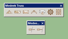
I haven't had any time this week or even this weekend to dive back into it yet but the icons for the Medeek Tools Menu (trim and extend for now) will look like this:

#2297
Version 1.6.7 - 07.21.2016
- Added a counter battens option within the battens menu for common, scissor and vaulted trusses.
- Battens (at peak) can be offset from peak.
- Peak-to-Eave spacing enabled when "battens at peak" option is selected.

This was a very small update so I just tucked it into the latest revision.

#2298
I can add another input field into the menu which will allow the offset from the peak:

Offset from Peak (mm):

I can also put in another option that will allow for the equal spacing between peak and eave battens with the spacing input serving as the max. batten spacing if this option is enabled:

Spacing Peak-to-Eave: YES/NO

I think this will then give you the flexibility you need to make this feature actually useful in real world applications.

Another thing to note is that the battens will work with the roof returns option but I currently have no logic in place to deal with the extension at the eave.  I may need to give this some more thought:

#2299
Version 1.6.7 - 07.21.2016
- Added a counter battens option within the battens menu for common, scissor and vaulted trusses.


View model here:

https://3dwarehouse.sketchup.com/model.html?id=3bb5c81a-ffd0-4f2f-8cf0-34bf6279428e

Counter battens can be applied with our without sheathing.  The counter battens are centered on the trusses below therefore their spacing is not independently controlled. 

Based on my research it appears that counter battens are usually only applied when battens are laid on top of a sheathed roof.  However I have left the option open to apply them without the sheathing in case one wanted to apply them directly to the truss top chords over a vapor barrier.
#2300
Version 1.6.6 - 07.15.2016
- Added roof battens option within the advanced options menu for common, scissor and vaulted trusses.
- Battens can be offset from the fascia board.
- Battens at peak option enabled.


View model here:

https://3dwarehouse.sketchup.com/model.html?id=e7f7a812-53da-4c57-b40a-b28bbacf96e2

Currently this feature is only available for truss roofs, I still need to add it to hip and gable rafter roofs.

If sheathing is enabled with battens, the battens are placed on top of the sheathing.
#2301
This is a quick study of a post frame roof using doubled trusses with 2x6 purlins @ 24" o/c.  This is pretty typical for a  pole barn or post frame building constructed locally:


View model here:

https://3dwarehouse.sketchup.com/model.html?id=0240f563-8350-460d-b07c-9f7dae117782

Notice how the rake and fascia boards are raised above the trusses so that they are flush with the roof plane and purlins.  The overhang can be achieved a number of ways but one method is to extend rafters from an inboard purlin and also attach to the post as shown. 


There are a number of other ways to frame the overhang, a quick search online will attest to this.  Sometimes a header is used between posts which allows for a truss spacing which is closer than the post spacing.

Purlins position right at the peak seems fairly standard, based on some plansets that I have.

When you add end walls with posts you can usually eliminate the doubled truss at the gable ends and you often will see a gable end truss that has girts (horiz. members) instead of studs.


With a purlin roof I almost need to create a separate menu item and module to properly deal with it.

Here is an interesting double truss design but with scissor trusses:

#2302
Here is a quick study on a garage slab that slopes 3" over about 24':


View model here:

https://3dwarehouse.sketchup.com/model.html?id=e4d46f5d-d5cc-4ba9-9439-39b3fe281e00

What to do with the slope at the garage door?  I've flattened it out but that leaves a line in the slab.

At the side door entrance the right side of the slab is about 3/8" higher than the left side.  Entrances that are parallel to the slope will have this property (problem?).

At the rear of the garage the slab is 6" below the top of the foundation and at the garage door it is 9" below the top.  Perusing through different plan sets I've collected over the years this seems pretty typical for the slope (1/8" in 12").

I think I should probably make the slope an option so those that want to model it can.

Rather than make the slope a percent grade or degrees I think it would be easiest to let the users specify a total rise or drop for the entire slab.
#2303
This is an example of a 24' x 24' garage that I would like to build on my property this summer or the next. 


View model here:

https://3dwarehouse.sketchup.com/model.html?id=77329ddc-a170-4dde-945e-4e413304f620

I created the foundation and roof with minimal effort using my own plugins.  The walls were created initially with the housebuilder plugin however I then manually edited the walls.  Note that the top plates overlap properly as they should.

Also note that the garage door wall is a double portal frame.  I would like for my wall plugin to automatically create this standard type of portal frame (PFH) both single and double (ie. Garage Door Option). Notice the embedded Simpson Strong-Tie STHD14 holdowns.

I like to use 2x jamb boards around the door perimeters when the stem wall projects above the concrete slab, this may be atypical constructon for others.  Local contractors like to embed a pressure treated nailer into the concrete.

In theory I should be able to create this exact model using the Foundation, Wall and Truss Plugin and do it all within 5 minutes or less.  That is the goal.

With the wall plugin I will have the standard linear wall tool but I would also like to have a rectangle wall tool that will immediately throw up 4 walls given three user selected points, similar to the truss and roof plugins.
#2304
The blockout methods seem to be all over the board, I've even talked with some of my engineering friends and the response is mixed there as well.  I guess I just need to provide the option for any of these three configurations within the plugin.  Sometimes I feel that I get bogged down in the details but I hope some of this level of detail is appreciated.

The other issue I'm having with slabs within garage spaces is the slope of the slab.  I'm trying to determine if is worth trying to incorporate a slope into the slab as it would actually be poured. As far as I know there is not a minimum slope specified for garage floors in the IRC 2015 or earlier only this fairly general statement:

The area of the floor used for parking of automobiles or other vehicles shall be sloped to facilitate the movement of liquids to a drain or toward the main vehicle entry doorway.

Typically the garage slope is 1/8" per foot or 1:96, how critical is this to you the user of the plugin?  Flat would be easier to program but then your blocked out entries on the side of a garage would be only theoretical.
#2305
I should point out I've also seen a sort of a combination of the two options where the blockout does not extend to the footing but a thickened edge is employed at the slab/door interface and the thickened edge is typically 2x the slab thickness, or called out as a minimum dimension of 8".

Option 3:

#2306
I'm trying to determine which is the preferred method of blocking out a stemwall foundation for garage doors where a slab will be poured in the garage.  I've seen it done both ways.  Option 1 does not typically block all of the stemwall out and seems to be more common in locations where the frostline is deeper (24" or deeper).  Option 2 completely blocks out the stemwall at the garage door and then a thicken edge is poured where the slab meets the footing at the garage door.  From a structural point of view which is the better method and also from a construction point of view what are the pros and cons?

Option 1:


Option 2:


View model here:

https://3dwarehouse.sketchup.com/model.html?id=9052ff81-b3c2-4aef-b40a-39a8be9e520b
#2307
When the user selects a type B footing (stemwall foundation) a keyway is inserted between the stemwall and footing:


View model here:

https://3dwarehouse.sketchup.com/model.html?id=242c0e7d-db46-43b7-baf6-ce322a842e4e
#2308
Version 1.0.2 - 07.08.2016
- Added stemwall foundation type (rectangular outline only).
- Enabled post and pier interior floor beam(s) with a strip footing.
- Added brick ledge option to stemwall foundation.


View model here:

https://3dwarehouse.sketchup.com/model.html?id=0b7542df-71cd-4908-8aef-731c9bb95f8a
#2309
Version 1.6.5 - 07.07.2016
- Added energy/raised heels for polynesian truss type (1 variant: vertical w/ strut).
- Fixed HTML truss selector menu so that window size no longer truncates truss images.


View model here:

https://3dwarehouse.sketchup.com/model.html?id=c4ecc314-9702-4c99-9148-ca0790178583
#2310
If an exclusion area is simply a hole in the slab then it is probably easiest just to push/pull a hole in the slab.  However, if the exclusion area is a large opening with footings required at the perimeter then that is a different matter.  It might look something like this:


View model here:

https://3dwarehouse.sketchup.com/model.html?id=2348e047-381b-4cb9-94fe-5b8dc8155413

Note how the opening bisects the interior footing, which does potentially complicate any algorithm that would generate the hole and perimeter footing.  I will have to give this some more thought...