Version 2.2.6 - 12.16.2018
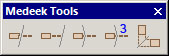
- Added the Miter Cut icon to the Medeek Tools toolbar.
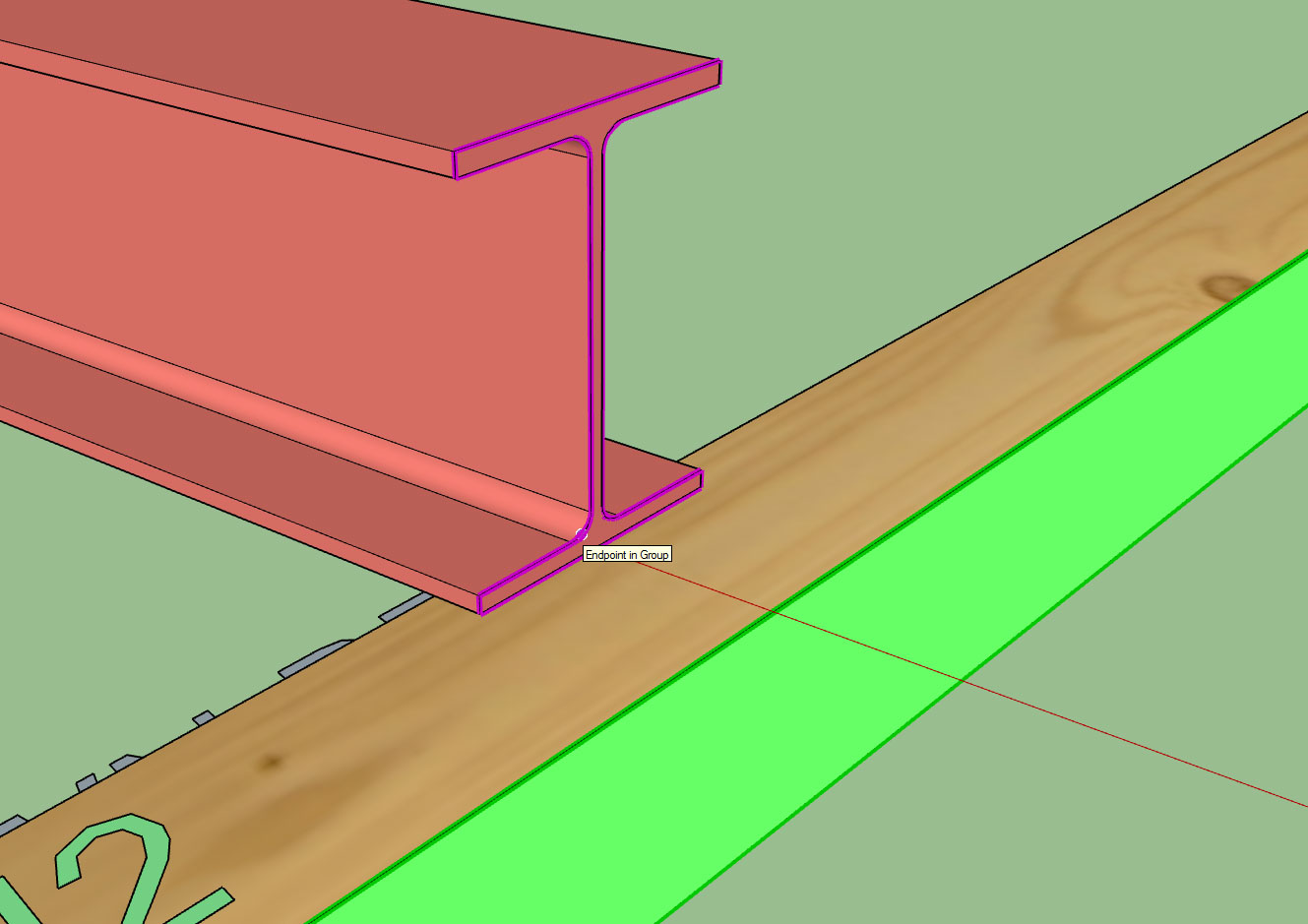
- Added the Miter Cut function for (solid) groups and components.
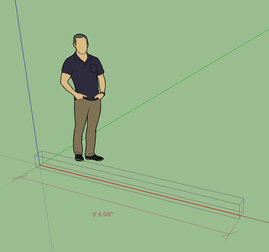
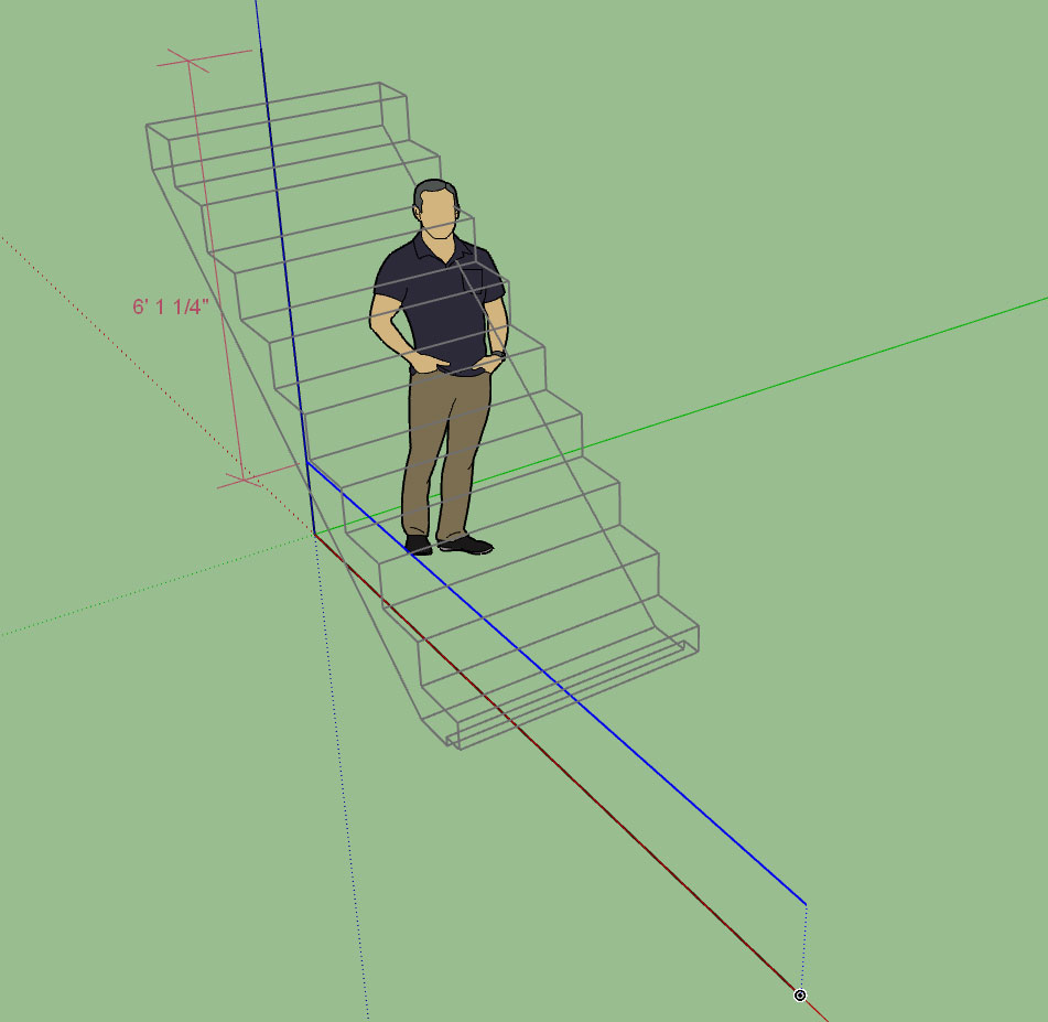
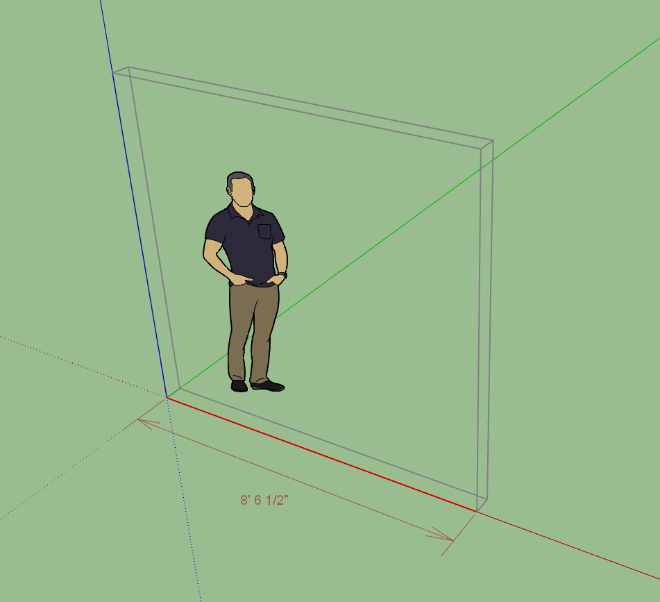
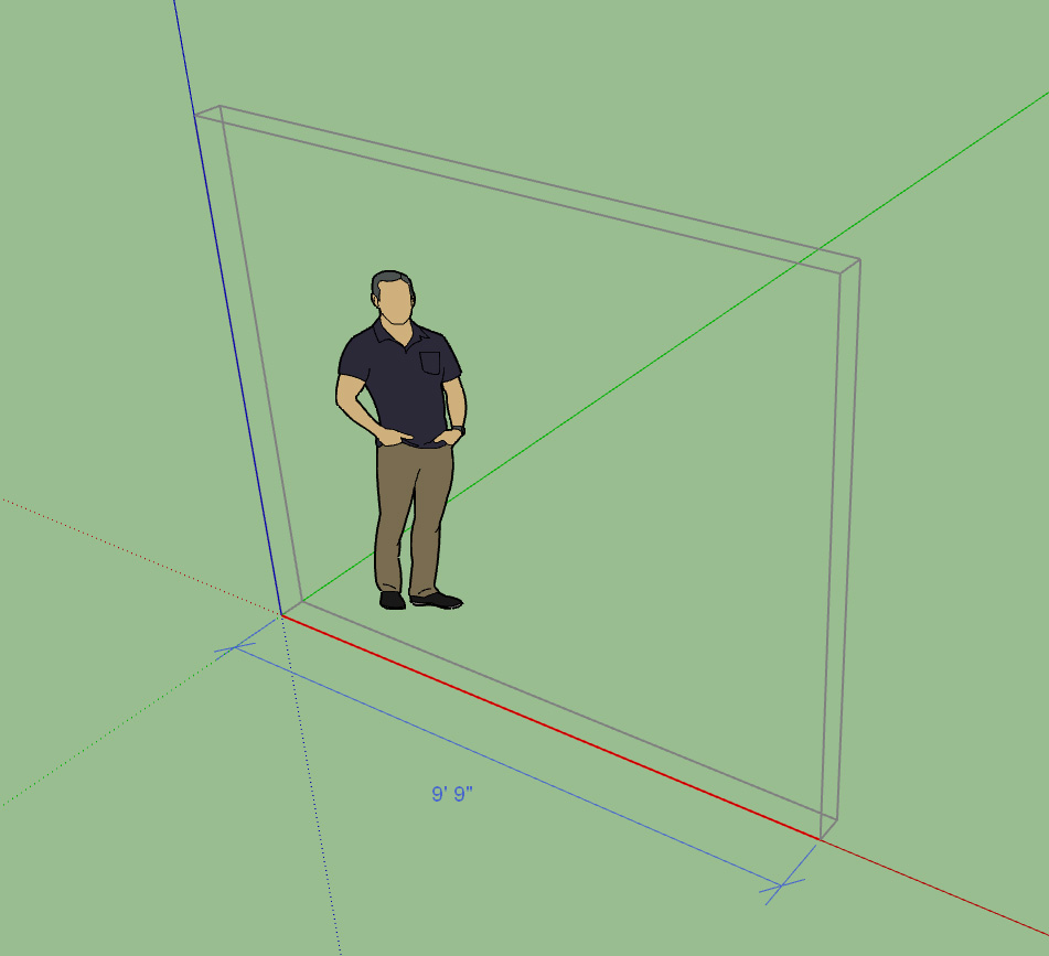
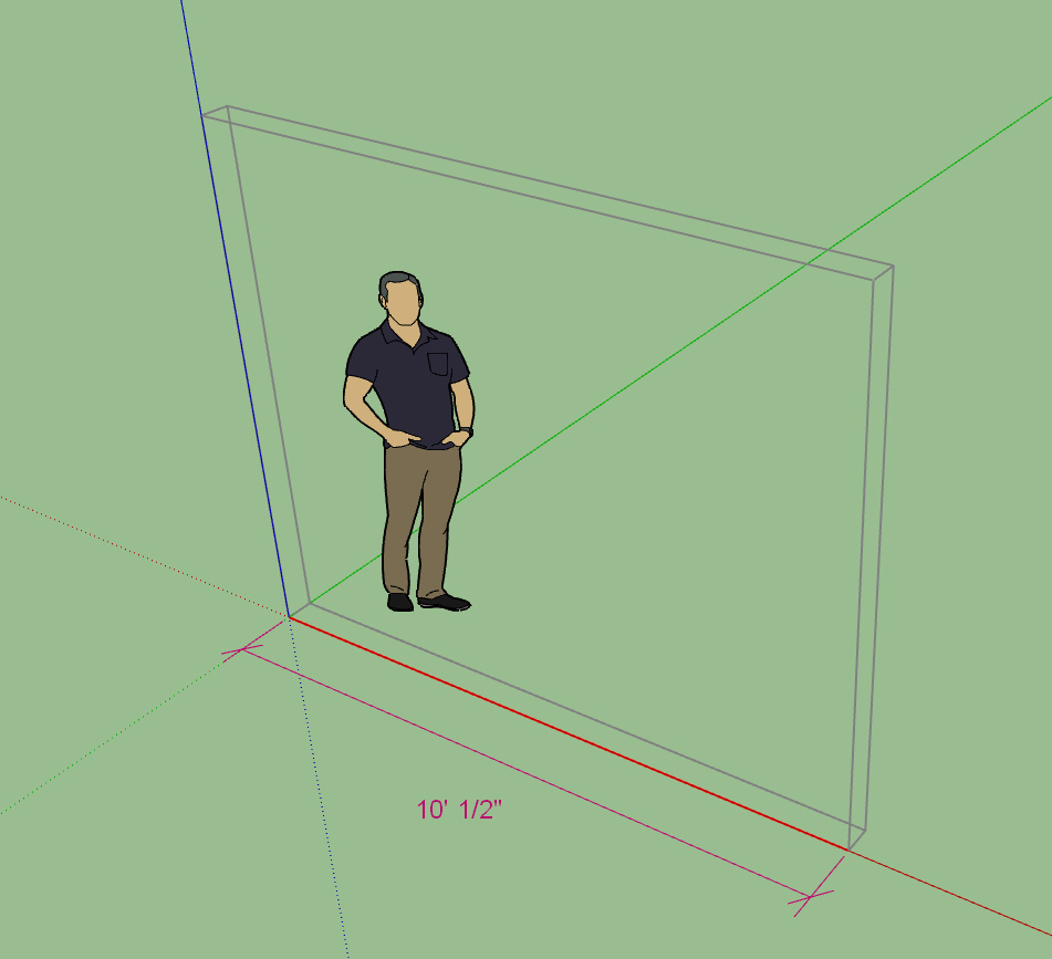
- Enabled temporary (construction) dimensions for trusses, roofs and floor assemblies.
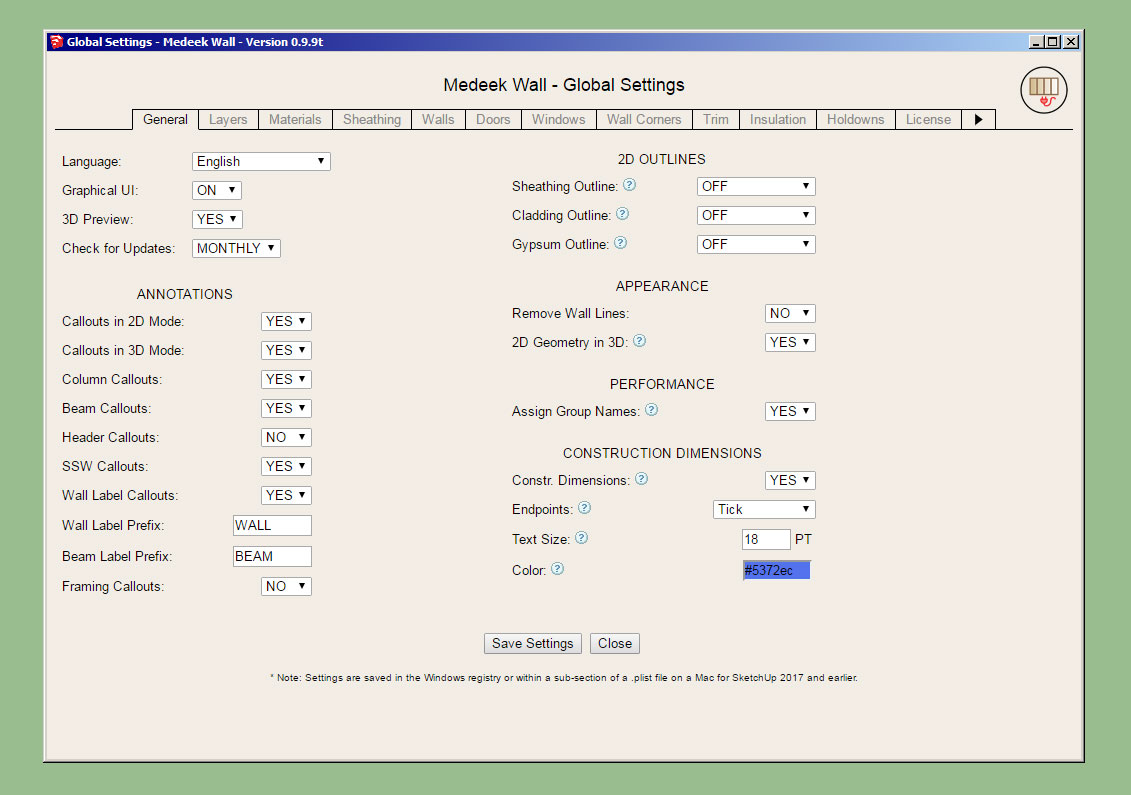
- Added a section in the General tab of the global settings for configuring construction dimensions.
Tutorial 12 - Miter Cut:
- Added the Miter Cut icon to the Medeek Tools toolbar.
- Added the Miter Cut function for (solid) groups and components.
- Enabled temporary (construction) dimensions for trusses, roofs and floor assemblies.
- Added a section in the General tab of the global settings for configuring construction dimensions.
Tutorial 12 - Miter Cut: