Subject
Customer
Location
Job No.
Engr.
Rev.
Date
Page

Wind Load Report

1. Site & Building Data

Roof Type: Gable  
Wind Speed (ult): 115 mph
Exposure Category: C  
Enclosure Class: Enclosed  
Building Width (W): 39.8 ft.
Building Length (L): 39.3 ft.
Eave Height (he): 18 ft.
Foundation Height (hf): 2 ft.
Roof Pitch: 4 /12
Eave Overhang (OHe): 2.5 ft.
Gable Overhang (OHg): 2.5 ft.

2. Parameters & Coefficients

Topographic Factor (Kzt): 1.0
Directionality Factor (Kd): .85
Roof Angle (θ): 18.43 deg.
Mean Roof Height (h): 21.32 ft.
Ridge Height (hr): 24.63 ft.
Pos. Internal Pressure (+GCpi): +0.18  
Neg. Internal Pressure (-GCpi): -0.18  
Velocity Pressure Exp. Coeff. (Kh): 0.91 @ z=h
Velocity Pressure (qh): 26.30 psf
End Zone Width (a): 3.00 ft.
Zone 2/2E Dist.: 19.90 ft.

3. Design Assumptions and Notes

Code Standard: ASCE 7-10
Geometry: Regular-Shaped Bldg.
Height Class: Low-Rise Building
Notes:

4. Design Loads

Top Chord Dead Load: 10 psf
Bottom Chord Dead Load: 3 psf
Truss/Rafter Spacing: 24 in. o/c

4. Design Wind Pressures: MWFRS Envelope Procedure


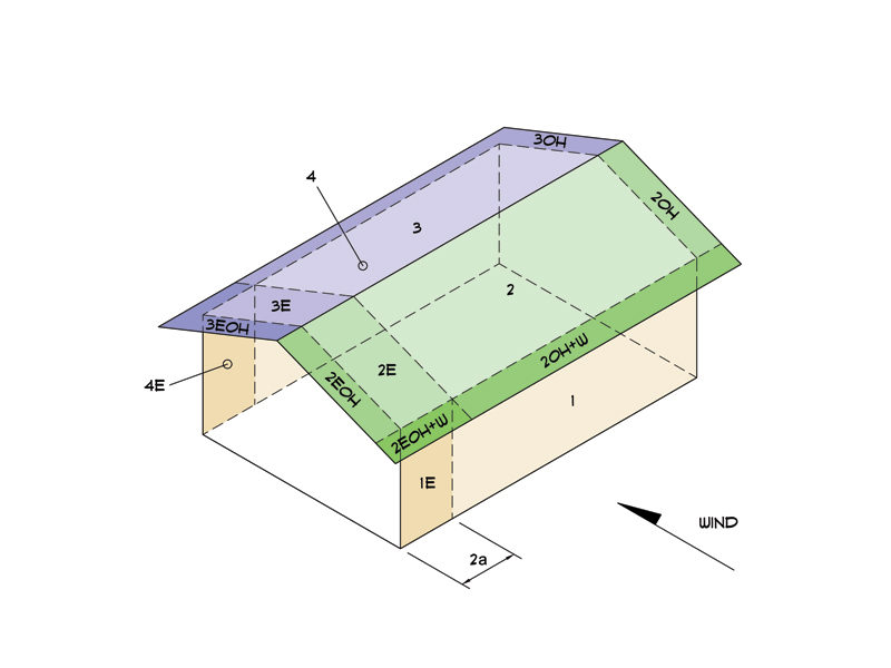
Load Case A: Transverse Direction
Surface GCpf Design Pressure (psf)
(w/ +GCpi) (w/ -GCpi)
1 0.52 8.85 18.32
2 -0.69 -22.89 -13.42
3 -0.47 -17.06 -7.59
4 -0.42 -15.66 -6.19
1E 0.78 15.79 25.26
2E -1.07 -32.88 -23.41
3E -0.67 -22.45 -12.98
4E -0.62 -20.99 -11.52
2OH -0.69 -18.15
2EOH -1.07 -28.15
3OH -0.47 -12.32
3EOH -0.67 -17.71
2OH+W -0.69/-0.7 -35.92
2EOH+W -1.07/-0.7 -45.92
a) (+) and (-) signs signify wind pressures acting toward & away from surfaces.
b) External Pressure Coefficients linearly interpolated from Fig. 28.4-1 ASCE 7-10.
c) Design building for all wind directions, 4 load patterns per load case.
d) Total horizontal shear shall not be less than that by neglecting roof wind forces.
e) Min. wind load for enclosed or partially enclosed bldg.: 16 psf wall, 8 psf roof.
f) Design pressures are for strength design, multiply by 0.6 for ASD.
Wind Loads REZA MONSEF 3024 McGraw Street 2024D267
Engineer Name ENGINEERING COMPANY INC.
Street Address City, CA 99999
ph. (800) 000-0000    www.website.com
-
7/15/2024 1
Subject
Customer
Location
Job No.
Engr.
Rev.
Date
Page

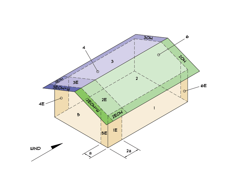
Load Case B: Longitudinal Direction
Surface GCpf Design Pressure (psf)
(w/ +GCpi) (w/ -GCpi)
1 -0.45 -16.57 -7.10
2 -0.69 -22.89 -13.42
3 -0.37 -14.47 -5.00
4 -0.45 -16.57 -7.10
5 0.40 5.79 15.26
6 -0.29 -12.36 -2.89
1E -0.48 -17.36 -7.89
2E -1.07 -32.88 -23.41
3E -0.53 -18.68 -9.21
4E -0.48 -17.36 -7.89
5E 0.61 11.31 20.78
6E -0.43 -16.05 -6.58
2OH -0.69 -18.15
2EOH -1.07 -28.15
3OH -0.37 -9.73
3EOH -0.53 -13.94
2EOH+W -1.07/-0.7 -46.56
3EOH+W -0.53/-0.7 -32.35
a) (+) and (-) signs signify wind pressures acting toward & away from surfaces.
b) External Pressure Coefficients linearly interpolated from Fig. 28.4-1 ASCE 7-10.
c) Design building for all wind directions, 4 load patterns per load case.
d) Total horizontal shear shall not be less than that by neglecting roof wind forces.
e) Min. wind load for enclosed or partially enclosed bldg.: 16 psf wall, 8 psf roof.
f) Design pressures are for strength design, multiply by 0.6 for ASD.


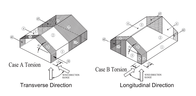
Torsional Load Cases
Surface Load Case GCpf Design Pressure (psf)
(w/ +GCpi) (w/ -GCpi)
1T A - 2.21 4.58
2T A - -5.72 -3.35
3T A - -4.26 -1.90
4T A - -3.92 -1.55
5T B - 1.45 3.81
6T B - -3.09 -0.72
a) (+) and (-) signs signify wind pressures acting toward & away from surfaces.
b) Pressures designated with a "T" are 25% of full design wind pressures.
c) Torsional loading shall apply to all 8 load patterns using the figures shown.
d) Design pressures are for strength design, multiply by 0.6 for ASD.
e) Torsional Design Exceptions: One story bldg. with h ≤ 30 ft,
   Two stories or less framed with light frame construction,
   Two stories or less with flexible diaphragms.
Wind Loads REZA MONSEF 3024 McGraw Street 2024D267
Engineer Name ENGINEERING COMPANY INC.
Street Address City, CA 99999
ph. (800) 000-0000    www.website.com
-
7/15/2024 2
Subject
Customer
Location
Job No.
Engr.
Rev.
Date
Page

5. Wind Load Calculations


1.) Lateral Loads - Transverse Direction:


Lateral Loads on Roof Diaphragm with Positive Internal Pressure
39.3 ft.
6.00 ft.
33.30 ft.
100.8 plf
75.2 plf
75.8 plf
42.5 plf
1696 lbs
1556 lbs
89.3 plf
67.9 plf
130.9 plf
91.1 plf
112.0 plf
72.2 plf
23.0 plf
18.0 plf
70.5 plf
49.1 plf
8.9 plf
6.2 plf
2.5 ft.
2.5 ft.
a) (-) signs signify wind lateral forces acting opposite to the direction of the arrows shown.
b) Strength design values multiplied by 0.6 to obtain ASD values.


Wind Base Shear (ASD)
Load Case A: Transverse Direction
Load Case Walls (lbs) Roof (lbs) Roof Overhangs (lbs) Total Lateral Load (lbs) R1 (lbs) R2 (lbs)
Positive Internal Pressure 4977 -1021 -704 3252 1696 1556
Negative Internal Pressure 4977 -1021 -704 3252 1696 1556
Roof Pressure = 0 4977 0 0 4977 2638 2339
Min. Pressures (8 psf, 16 psf) 3018 1251 336 4606 2303 2303
a) Bottom half of wall neglected in tributary area calculations.
b) Strength design values multiplied by 0.6 to obtain ASD values.
Wind Loads REZA MONSEF 3024 McGraw Street 2024D267
Engineer Name ENGINEERING COMPANY INC.
Street Address City, CA 99999
ph. (800) 000-0000    www.website.com
-
7/15/2024 3
Subject
Customer
Location
Job No.
Engr.
Rev.
Date
Page

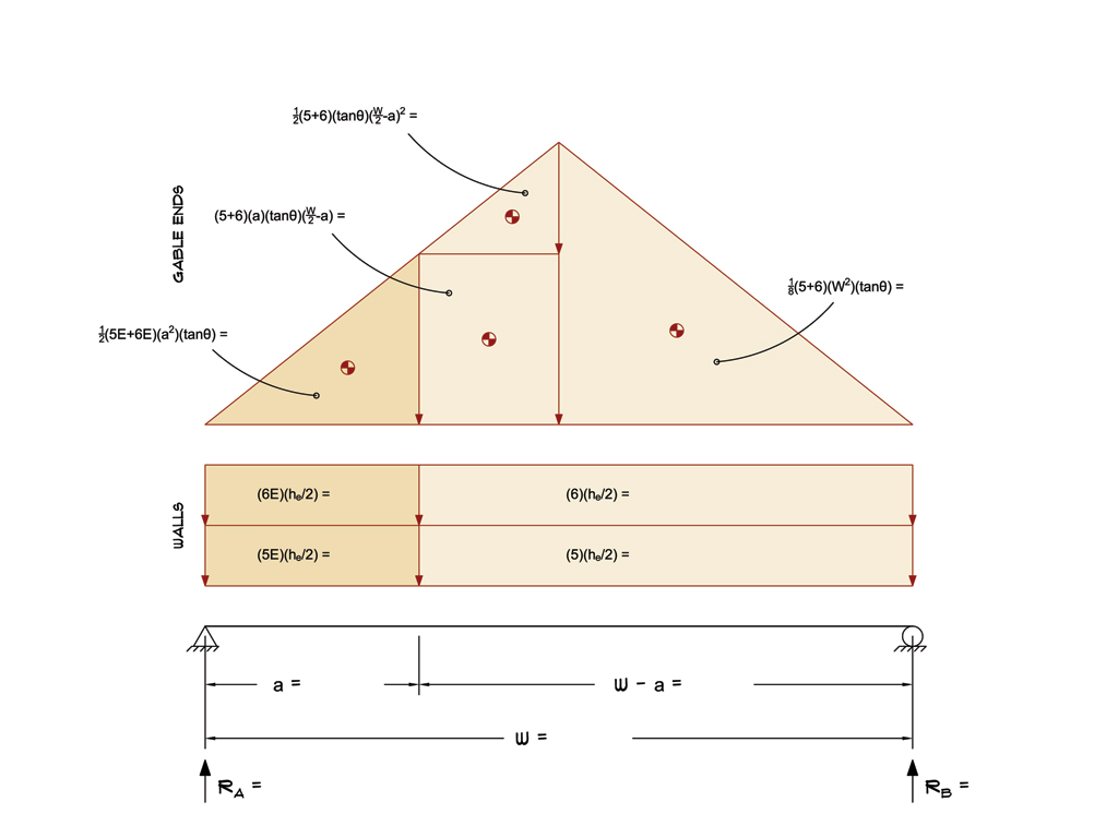
2.) Lateral Loads - Longitudinal Direction:


Lateral Loads on Roof Diaphragm with Positive Internal Pressure
39.8 ft.
3.00 ft.
36.80 ft.
77.0 plf
59.3 plf
54.3 plf
27.8 plf
24.6 lbs
184.0 lbs
518.4 lbs
718.8 lbs
2588 lbs
2458 lbs
a) (-) signs signify wind lateral forces acting opposite to the direction of the arrows shown.
b) Strength design values multiplied by 0.6 to obtain ASD values.
c) Where the length of building (L) exceeds 4X the mean roof height (h), wind drag forces should additionally be considered.


Wind Base Shear (ASD)
Load Case B: Longitudinal Direction
Load Case Walls (lbs) Gable Ends (lbs) Roof (lbs) Total Lateral Load (lbs) RA (lbs) RB (lbs)
Positive Internal Pressure 3600 1446 0 5046 2588 2458
Negative Internal Pressure 3600 1446 0 5046 2588 2458
Roof Pressure = 0 3600 1446 0 5046 2588 2458
Min. Pressures (8 psf, 16 psf) 3057 1267 0 4324 2162 2162
a) Bottom half of wall neglected in tributary area calculations.
b) Strength design values multiplied by 0.6 to obtain ASD values.
Wind Loads REZA MONSEF 3024 McGraw Street 2024D267
Engineer Name ENGINEERING COMPANY INC.
Street Address City, CA 99999
ph. (800) 000-0000    www.website.com
-
7/15/2024 4
Subject
Customer
Location
Job No.
Engr.
Rev.
Date
Page

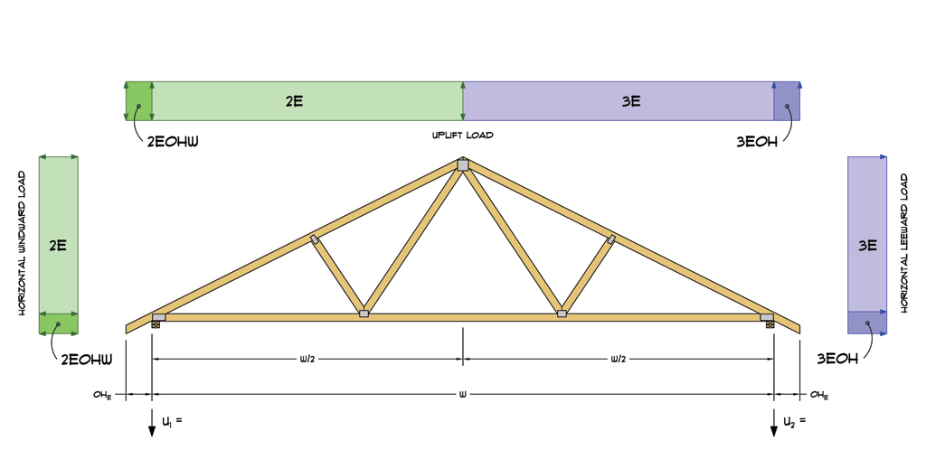
3.) Roof Truss Reactions:


Roof Truss/Rafter Reactions: Transverse End Zone
508 lbs
294 lbs
Max. Horz. ① = 127 lbs
Max. Uplift ① = 508 lbs
a) Strength design values multiplied by 0.6 to obtain ASD values.
b) Windward loads may be positive or negative depending on pitch of roof.


Roof Truss/Rafter Reactions (ASD)
w/ Positive Internal Pressure
Load Case Horizontal Load (lbs) Gross Uplift (lbs) Net Uplift (lbs) U1 (lbs) U2 (lbs)
Transverse Int. Zone 70 1099 389 267 122
Transverse End Zone 111 1512 802 508 294
Longitudinal Int. Zone 75 976 266 197 69
Longitudinal End Zone 127 1357 647 431 216
a) Gross Uplift calculations do not include any counteracting roof dead loads.
b) Net Uplift calculations include counteracting roof dead loads multiplied by 0.6 per load case (7) ASCE 7-10.
c) Strength design values multiplied by 0.6 to obtain ASD values for wind loads.
d) Loads based on truss spacing calculated at 24" o/c.
e) Negative values for horizontal load indicate load acting in windward direction (tranverse load cases).
f) Negative values for uplift indicate net downward force (zero uplift).


*Disclaimer: The calculations produced herein are for initial design and estimating purposes only. The calculations and drawings presented do not constitute a fully engineered design. All of the potential load cases required to fully design an actual structure may not be provided by this calculator. For the design of an actual structure, a registered and licensed professional should be consulted as per IRC 2012 Sec. R802.10.2 and designed according to the minimum requirements of ASCE 7-10. The wind load calculations provided by this online tool are for educational and illustrative purposes only. Medeek Design assumes no liability or loss for any designs presented and does not guarantee fitness for use.
Wind Loads REZA MONSEF 3024 McGraw Street 2024D267
Engineer Name ENGINEERING COMPANY INC.
Street Address City, CA 99999
ph. (800) 000-0000    www.website.com
-
7/15/2024 5